- 22 -
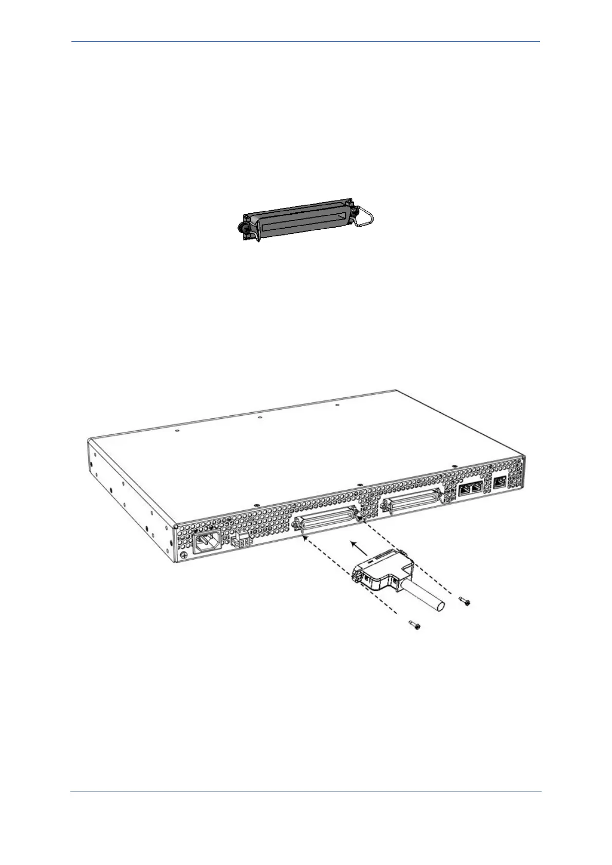
2. Connect the Patch Panel's 50-Pin D-Sub male connector to the device's 50-Pin D-Sub female
connector, located on the rear panel. Depending on the connector, secure it to the device's
connector using one of the following methods:
• Bail Locks:
a. Flip the two bail locks, located on either side of the connector, outwards.
b. Plug the male connector into the device's female connector.
c. Flip the two bail locks inwards onto the male connector.
Figure 16: Bail Locks on 50-Pin D-Sub Connector
• Coupling Nuts and Screws:
a. Using a Philips-head screwdriver, remove the two screws that are located on either
side of the connector.
b. Screw the coupling nuts (supplied) into the holes from where you removed the
screws.
c. Plug the male connector into the device's female connector.
d. Secure the connector by screwing the male connector's captive screws to the
coupling nuts.
Figure 17: Connecting Patch Panel to Device's 50-Pin D-Sub Connector
3. Connect your analog equipment to the Patch Panel, by plugging the analog equipment's RJ-11
connectors into the RJ-11 sockets on the Patch Panel's front panel.

 Loading...