Basic principles
BK11x0, BK125028 Version: 4.1
4.5 LEDs and connection
4.5.1 LEDs
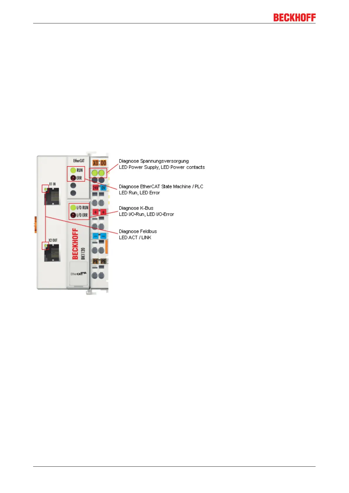
After switching on, the Bus Coupler immediately checks the connected configuration. Error-free start-up is
signaled by the red LED I/O ERR being extinguished. If the I/O ERR LED blinks, an error in the area of the
terminals is indicated. The frequency and number of flashes indicate the error code (see below).
The BK1120 / BK1150 Bus Coupler has a green LED at the RJ45 sockets, which indicates the fieldbus
status. The RUN and ERROR LEDs (for BK1120: center top, for BK1150: left row of the LED prism) indicate
the state of the EtherCAT state machine.
On the upper right hand side of the BK1120 are two more green LEDs that indicate the supply voltage. The
left hand LED indicates the presence of the 24V supply for the Bus Coupler. The right hand LED indicates
the presence of the supply to the power contacts. At the BK1150, the diagnostic LEDs are on the right side
of the LED prism, as shown in Fig. Diagnostic LEDs at Bus Coupler BK1120, BK1150.
Fig.19: Diagnostic LEDs at Bus Coupler BK1120
 Loading...