Home
Beckhoff
Adapter
BK11 0 Series
Beckhoff BK11 0 Series User Manual
4
of 1
of 1 rating
88 pages
Give review
Manual
Specs
To Next Page
To Next Page
To Previous Page
To Previous Page
Loading...
Parameterization and commissioning
BK11x0, BK1250
62
Version: 4.1
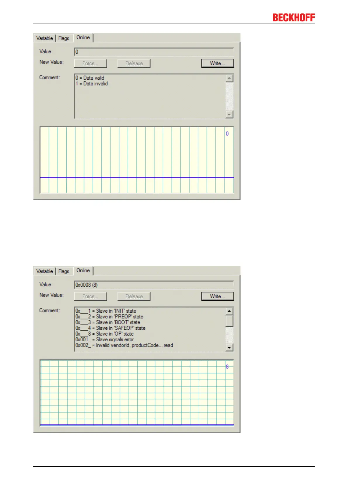
Fig.48: WCstate, "Online" tab
6.4.6
Online status (info data) - configuration overview
State, "Online" tab
Indicates the online status of the coupler.
Fig.49: State, "Online" tab
61
63
Table of Contents
Table of Contents
4
2 Foreword
7
Notes on the Documentation
7
Safety Instructions
8
Documentation Issue Status
9
Version Identification of Ethercat Devices
9
Fig. 1 EL5021 el Terminal, Standard IP20 IO Device with Batch Number and Revision ID (Since 2014/01)
11
Fig. 2 EK1100 Ethercat Coupler, Standard IP20 IO Device with Batch Number
11
Fig. 3 CU2016 Switch with Batch Number
11
Fig. 4 EL3202-0020 with Batch Numbers 26131006 and Unique ID-Number 204418
12
Fig. 5 EP1258-00001 IP67 Ethercat Box with Batch Number 22090101 and Unique Serial Number 158102
12
Fig. 6 EP1908-0002 IP76 Ethercat Safety Box with Batch Number 071201FF and Unique Serial Number 00346070
12
Fig. 7 EL2904 IP20 Safety Terminal with Batch Number/Date Code 50110302 and Unique Serial Num- Ber 00331701
12
Fig. 8 ELM3604-0002 Terminal with ID Number (QR Code) 100001051 and Unique Serial Number 44160201
13
3 Product Overview
14
Introduction
14
Fig. 9 Bus Couplers BK1120 and BK1150
14
Fig. 10 BK1250
15
Fig. 11 K-Bus_E-Bus
15
Technical Data
16
4 Basic Principles
17
System Properties
17
Fig. 12 Ethercat Telegram Structure
17
Fig. 13 Ethercat Topology
18
The Beckhoff Bus Terminal System
20
Coe Interface
21
Fig. 14 "Coe Online " Tab
22
Fig. 15 Startup List in the Twincat System Manager
23
Fig. 16 Offline List
24
Ethercat State Machine
25
Fig. 17 Online List
25
Fig. 18 States of the Ethercat State Machine
26
Leds and Connection
28
Leds
28
Fig. 19 Diagnostic Leds at Bus Coupler BK1120
28
Fig. 20 Diagnostic Leds at Bus Coupler BK1150
29
Fig. 21 Diagnostic Leds at Bus Coupler BK1250
29
Connection BK1120 and BK1150
32
Fig. 22 BK1120, BK1150 Connection
32
Connection BK1250
33
Fig. 23 BK1250 Connection
33
5 Mounting and Wiring
34
Instructions for ESD Protection
34
Fig. 24 Spring Contacts of the Beckhoff I/O Components
34
Installation on Mounting Rails
35
Fig. 25 Attaching on Mounting Rail
35
Fig. 26 Disassembling of Terminal
36
Fig. 27 Power Contact on Left Side
37
Installation Instructions for Enhanced Mechanical Load Capacity
38
Installation Positions
39
Fig. 28 Recommended Distances for Standard Installation Position
39
Power Supply, Potential Groups
40
Fig. 29 Other Installation Positions
40
Ethernet Cable
41
Fig. 30 Potential Diagram Ekxxxx
41
Ethercat Wiring
43
ATEX - Special Conditions (Extended Temperature Range)
44
ATEX Documentation
45
6 Parameterization and Commissioning
46
Start-Up Behavior of the Bus Coupler
46
Ekxxxx - Optional Distributed Clocks Support
46
Fig. 31 Flow Chart Showing Start-Up Behavior of the Bus Coupler
46
Fig. 32 DC Tab for Indicating the Distributed Clocks Function
46
Fig. 33 Advanced Distributed Clocks Settings in the Ethercat Master
47
KL Register Communication
48
Parameterization of KL Terminals
48
Fig. 34 Twincat Setting for Using this Component as Reference Clock
48
Fig. 35 Register Access on KL Terminals
49
Configuration of KL Terminals Via Ethercat
50
Fig. 38 Entry
50
Fig. 36 Insert Dialog
51
Fig. 37 Data Entry
52
Fig. 39 Complete Terminal Access
52
Online Parameterization of KL Terminals Via Coe
53
Fig. 40 Access to Two KL Terminals
53
Fig. 41 Online Coe Directory of the Bk11X0
54
Online Parameterization of KL Terminals Via Aoe
55
Fig. 42 Activation of the Aoe Netid
55
Beckhoff Coupler Tables
56
Fig. 43 Table 9 with Terminal Type
57
Twincat System Manager
58
BK1120, BK1150 - Configuration Overview
58
Fig. 44 Twincat Tree Showing BK1120 as Example
58
BK1250 - Configuration Overview
59
Fig. 45 Twincat Tree BK1250
59
Inputs - Configuration Overview
60
Outputs - Configuration Overview
60
Fig. 46 Couplerstate, "Online" Tab
60
Status of the Working Counter (Wc State) - - Configuration Overview
61
Fig. 47 Couplercrtl, "Online" Tab
61
Online Status (Info Data) - Configuration Overview
62
Fig. 48 Wcstate, "Online" Tab
62
Fig. 49 State, "Online" Tab
62
ADS Address (Adsaddr) - Configuration Overview
63
Fig. 50 Adsaddr, "Online" Tab
63
Ethercat Cycle Time - Configuration Overview
64
Object Description
64
Fig. 51 BK1250, "BK1250" Tab
64
Mapping the Bus Terminals
74
Process Image Example
75
Fig. 52 Configuration Example for Explaining the Process Image
75
KS2000 Configuration Software
76
Example: Parameterization with the KS2000 Configuration Software
76
Fig. 53 Configuration Software KS2000
76
Fig. 54 Twincat System Manager: Ethercat Tab for Box Bk11X0/Bk1250
77
Fig. 55 Dialog "Ethercat", "Advanced Settings", "Aoe
77
Fig. 56 Twincat System Manager: "Mailbox" Dialog, Transfer of Amsservernetid
78
Fig. 57 KS2000: "ADS" Tab, Enter the Amsservernetid
78
Fig. 58 Confirmation of Successful Communication Test
79
7 Error Handling and Diagnosis
80
Error Messages to the Ethercat Master
80
Fig. 59 Switching the Logger Window On/Off
80
Fig. 60 Display of the Error Message al Status Code '0X0003' in the Logger Window
80
Fig. 61 Display of the Error Message al Status Code '0X001E - Invalid SM in Cfg' in the Logger Win- Dow
80
8 Appendix
81
General Operating Conditions
81
ATEX Documentation
82
UL Notice
82
Test Standards for Device Testing
84
Firmware Compatibility
85
Support and Service
86
List of Illustrations
87
4
Based on 1 rating
Ask a question
Give review
Questions and Answers:
Need help?
Do you have a question about the Beckhoff BK11 0 Series and is the answer not in the manual?
Ask a question
Beckhoff BK11 0 Series Specifications
General
Brand
Beckhoff
Model
BK11 0 Series
Category
Adapter
Language
English
Related product manuals
Beckhoff BK3 0 Series
90 pages
Beckhoff BK1120
88 pages
Beckhoff BK3100
90 pages
Beckhoff BK3110
90 pages
Beckhoff BK3120
90 pages
Beckhoff BK3150
90 pages
 Loading...