Basic Function Principles
BK52x0 and LC5200 13Version: 2.0.0
K-Bus
The K-Bus is the data path within a terminal strip. The K-Bus is led through from the Bus Coupler through all
the terminals via six contacts on the terminals' side walls. The end terminal terminates the K-Bus. The user
does not have to learn anything about the function of the K-Bus or about the internal workings of the
terminals and the Bus Coupler. Many software tools that can be supplied make project planning,
configuration and operation easy.
Potential feed terminals for isolated groups
The operating voltage is passed on to following terminals via three power contacts. You can divide the
terminal strip into arbitrary isolated groups by means of potential feed terminals. The potential feed terminals
play no part in the control of the terminals, and can be inserted at any locations within the terminal strip.
Up to 64Bus Terminals can be used in a terminal block, with optional K-Bus extension for up to 256Bus
Terminals. This count does include potential feed terminals, but not the end terminal.
Bus Couplers for various fieldbus systems
Various Bus Couplers can be used to couple the electronic terminal strip quickly and easily to different
fieldbus systems. It is also possible to convert to another fieldbus system at a later time. The Bus Coupler
performs all the monitoring and control tasks that are necessary for operation of the connected Bus
Terminals. The operation and configuration of the Bus Terminals is carried out exclusively by the Bus
Coupler. Nevertheless, the parameters that have been set are stored in each Bus Terminal, and are retained
in the event of voltage drop-out. Fieldbus, K-Bus and I/O level are electrically isolated.
If the exchange of data over the fieldbus is prone to errors or fails for a period of time, register contents (such
as counter states) are retained, digital outputs are cleared, and analog outputs take a value that can be
configured for each output when commissioning. The default setting for analog outputs is 0V or 0mA. Digital
outputs return in the inactive state. The timeout periods for the Bus Couplers correspond to the usual
settings for the fieldbus system. When converting to a different bus system it is necessary to bear in mind the
need to change the timeout periods if the bus cycle time is longer.
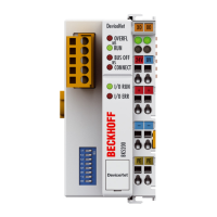
The interfaces
A Bus Coupler has six different methods of connection. These interfaces are designed as plug connectors
and as spring-loaded terminals.
 Loading...