Parameterization and Commissioning
BK52x0 and LC5200 31Version: 2.0.0
5 Parameterization and Commissioning
5.1 Start-up behaviour of the Bus Coupler
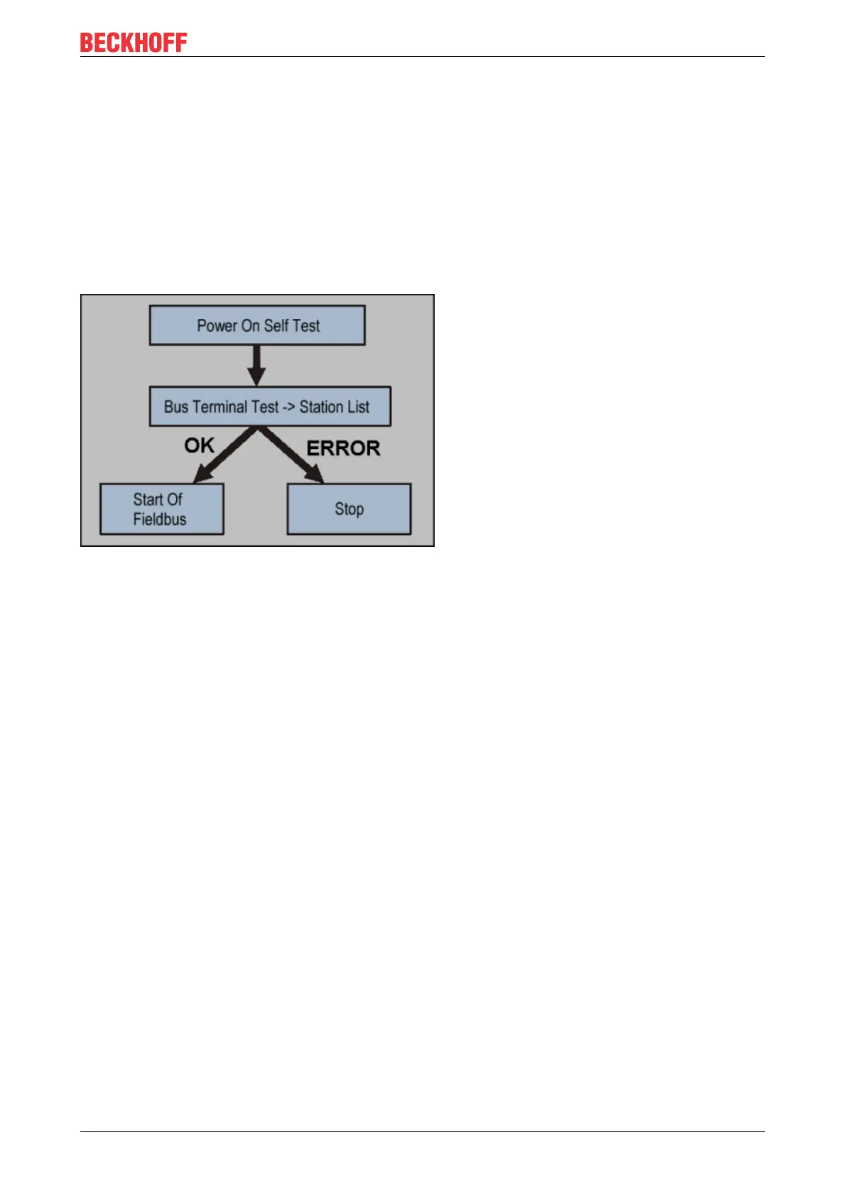
Immediately after being switched on, the Bus Coupler checks, in the course of a self-test, all the functions of
its components and the communication on the K-bus/E-bus. The red I/O LED blinks while this is happening.
After completion of the self-test, the Bus Coupler starts to test the attached Bus Terminals (the "Bus
Terminal Test"), and reads in the configuration. The Bus Terminal configuration is used to generate an
internal structure list, which is not accessible from outside. In case of an error, the Bus Coupler enters the
Stop state. Once the start-up has completed without error, the Bus Coupler enters the fieldbus start state.
Fig.18: Start-up behaviour of the Bus Coupler
The Bus Coupler can be made to enter the normal operating state by switching it on again once the fault has
been rectified.
5.2 Peripheral Data in the Process Image
After being switched on, the Bus Coupler determines the configuration of the inserted input/output terminals.
The assignment of the physical slots for the input/output channels and the addresses in the process image is
carried out automatically by the Bus Coupler.
The Bus Coupler creates an internal assignment list, in which the input/output channels have a specific
position in the process image. A distinction is made here according to inputs and outputs, and according to
bit-oriented (digital) and byte-oriented (analog or complex) signal processing.
Two groups are created, one for inputs and the other for outputs. Each group has the byte-oriented channels
in ascending sequence starting from the lowest address. The bit-oriented channels are placed after this
block.
Digital signals (bit-oriented)
The digital signals are bit-oriented. This means that one bit in the process image is assigned to each
channel. The Bus Coupler creates a memory area containing the current input bits, and ensures that the bits
in a second memory area dedicated to the output channels are written out immediately.
The details of the assignment of the input and output channels to the controller's process image is explained
fully with the aid of an example in the appendix.
Analog signals (byte-oriented)
The processing of analog signals is always byte-oriented. Analog input and output values are represented in
memory by two bytes each. The values are represented in "SIGNED INTEGER" or "two's complement". The
numerical value "0" stands for input/output value "0V", "0mA" or "4mA". The maximum value of an output
 Loading...