Parameterization and Commissioning
BK52x0 and LC520032 Version: 2.0.0
or input value is represented, according to the standard settings, by "7FFF" hex. Negative input/output
values, e.g. -10V are mapped as "1000" hex. The intermediate values are correspondingly proportional. A
range with a resolution of 15bits is not achieved for all input and output stages. With an actual resolution of
12bits, the last 3bits for outputs have no effect and for inputs they are read "0". Each channel also has a
control and status byte. The control and status byte is the highest value byte. Version 2.0 of the DeviceNet
coupler does not permit the control and status byte to be read. An analog channel is represented in the
process image by 2bytes. The following versions permit expansion of a channel's data width by means of
the KS2000 configuration software.
Special signals and interfaces
A Bus Coupler supports Bus Terminals with other interfaces such as RS232, RS485, incremental encoder
and others. These signals can be considered similarly to the analog signals named above. For some special
signals the bit width of 16 is not sufficient. The Bus Coupler can support any byte width.
Default assignment of inputs/outputs to the process image
Once it has been switched on, the Bus Coupler finds out how many Bus Terminals are inserted, and creates
an assignment list. The analog and digital channels, divided into inputs and outputs, are assembled into
separate parts of this list. The assignment starts on the left next to the Bus Coupler. The software in the Bus
Coupler collects the individual entries for each of the channels in order to create the assignment list counting
from left to right.
Four groups are distinguished in the assignment
Functional type of the channel Assignment level
1. Analog outputs assignment by bytes
2. Digital outputs assignment by bits
3. Analog inputs assignment by bytes
4. Digital inputs assignment by bits
Complex multi-byte signal Bus Terminals are represented as analog inputs or outputs.
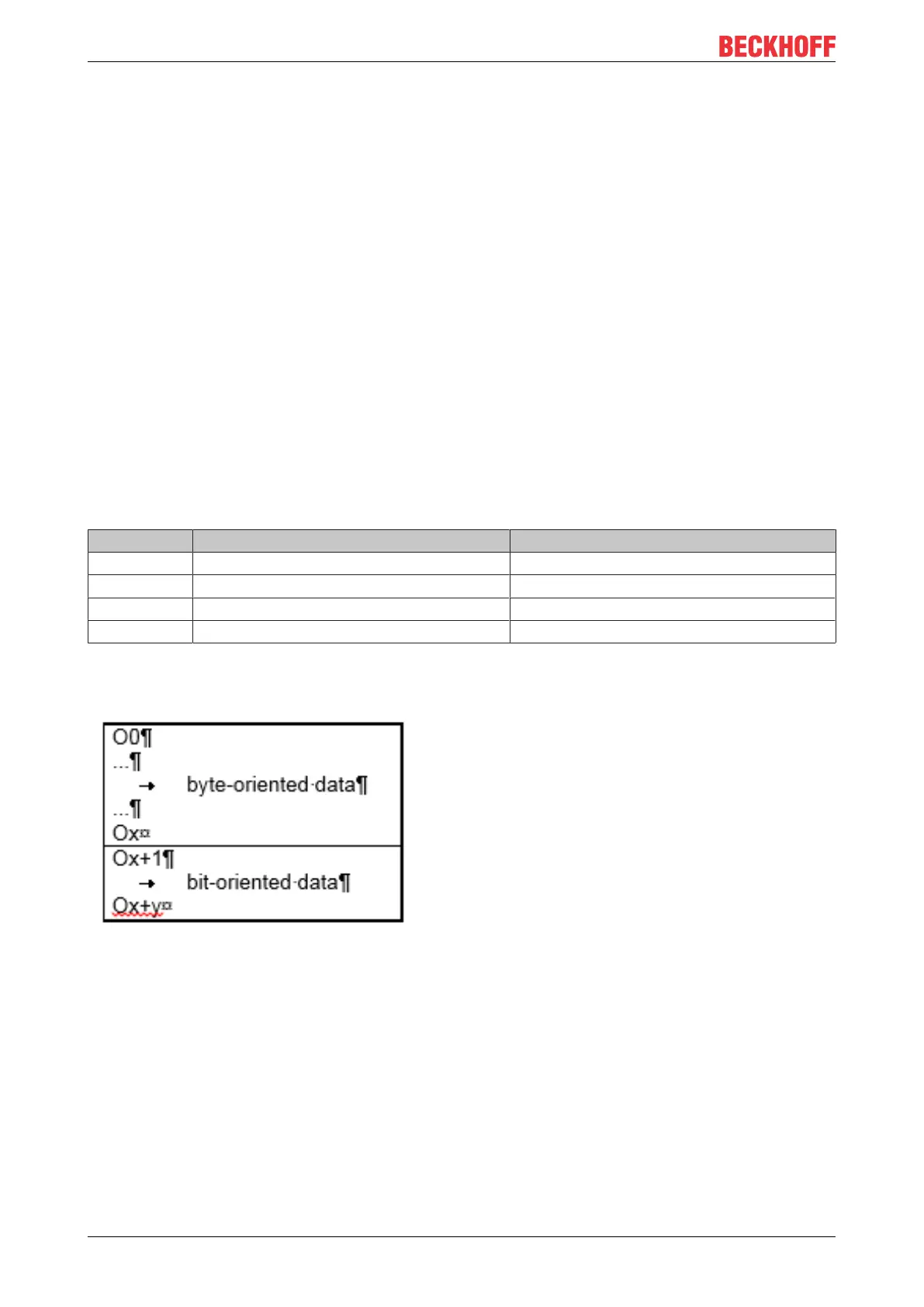
The distribution of the process image in the Bus Coupler in overview:
Fig.19: Output data in the Bus Coupler
 Loading...