Appendix
BK52x0 and LC5200 41Version: 2.0.0
6 Appendix
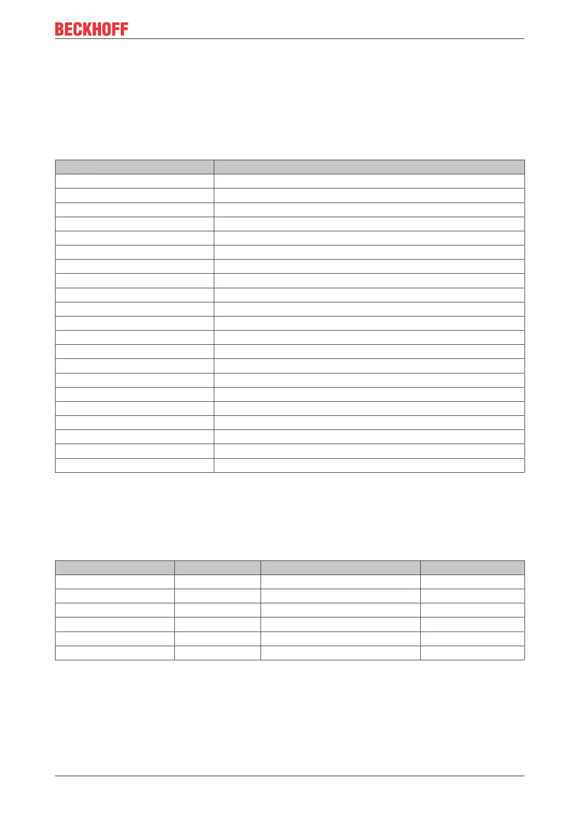
6.1 Composition of a process image in the Bus Coupler
An example shows the assignment of input and output channels to the process image. The sample
construction should consist of the following bus - terminal - assemblies:
Position Functional groups on the rail
POS01 Bus Coupler
POS02 Digital inputs, 2 channels
POS03 Digital inputs, 2 channels
POS04 Digital inputs, 2 channels
POS05 Digital inputs, 2 channels
POS06 Digital inputs, 2 channels
POS07 Digital outputs, 2 channels
POS08 Digital outputs, 2 channels
POS09 Digital outputs, 2 channels
POS10 Analog inputs, 2 channels
POS11 Analog outputs, 2 channels
POS12 Analog outputs, 2 channels
POS13 Analog inputs, 2 channels
POS14 Power feed terminal
POS15 Digital inputs, 2 channels
POS16 Digital inputs, 2 channels
POS17 Digital inputs, 2 channels
POS18 Digital outputs, 2 channels
POS19 Digital outputs, 2 channels
POS20 Analog outputs, 2 channels
POS21 End terminal
By default, DeviceNet only supports signal channels that are 16 bits wide. The STATUS/CONTROL BYTE is
not available. This means, for example, that an analog input terminal with 2 channels appears in the process
image with 2 x 16bits. The images have corresponding differences with respect to byte addresses and
assignments.
Area for byte-oriented data, analog outputs
Relative byte address Bit position Process image in the controller Position in the block
0, 1 none O0, O1 POS11
2, 3 none O2, O3 POS11
4, 5 none O4, O5 POS12
6, 7 none O6, O7 POS12
8, 9 none O8, O9 POS20
10, 11 none O10, O11 POS20
 Loading...