Appendix
BK52x0 and LC520042 Version: 2.0.0
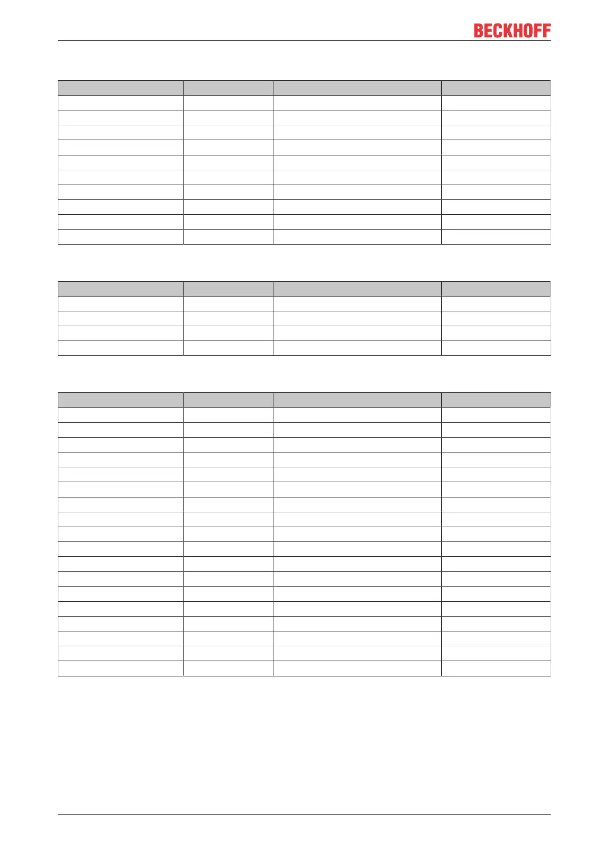
Area for bit-oriented data, digital outputs
Relative byte address Bit position Process image in the controller Position in the block
12 0 O12 POS07
12 1 O12 POS07
12 2 O12 POS08
12 3 O12 POS08
12 4 O12 POS09
12 5 O12 POS09
12 6 O12 POS18
12 7 O12 POS18
13 0 O13 POS19
13 1 O13 POS19
Area for byte-oriented data, analog inputs
Relative byte address Bit position Process image in the controller Position in the block
0, 1 none I0, I1 POS10
2, 3 none I2, I3 POS10
4, 5 none I4, I5 POS13
6, 7 none E6, E7 POS13
Area for bit-oriented data, digital inputs
Relative byte address Bit position Process image in the controller Position in the block
4 0 E4 POS01
4 1 E4 POS1
4 2 E4 POS2
4 3 E4 POS2
4 4 E4 POS3
4 5 E4 POS3
4 6 E4 POS4
4 7 E4 POS4
5 0 E5 POS5
5 1 E5 POS5
5 2 E5 POS6
5 3 E5 POS6
5 4 E5 POS15
5 5 E5 POS15
5 6 E5 POS16
5 7 E5 POS16
6 0 I6 POS17
6 1 I6 POS17
Positions POS14 and POS21 are not relevant to data exchange. They do not appear in the list. If a byte is
not fully utilized, e.g. E8, the Bus Coupler pads the remaining bits of the byte with zeros.
 Loading...