Mounting and wiring
EK110x, EK15xx46 Version: 3.6
Terminal housing ELxxxx, KLxxxx ESxxxx, KSxxxx
Wire size width (single core wires) 0.08 ... 2.5mm
2
0.08 ... 2.5mm
2
Wire size width (fine-wire conductors) 0.08 ... 2.5mm
2
0,08 ... 2.5mm
2
Wire size width (conductors with a wire end sleeve) 0.14 ... 1.5mm
2
0.14 ... 1.5mm
2
Wire stripping length 8 ... 9mm 9 ... 10mm
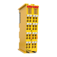
High Density Terminals (HD Terminals [
}
44]) with 16 terminal points
The conductors of the HD Terminals are connected without tools for single-wire conductors using the direct
plug-in technique, i.e. after stripping the wire is simply plugged into the terminal point. The cables are
released, as usual, using the contact release with the aid of a screwdriver. See the following table for the
suitable wire size width.
Terminal housing High Density Housing
Wire size width (single core wires) 0.08 ... 1.5mm
2
Wire size width (fine-wire conductors) 0.25 ... 1.5mm
2
Wire size width (conductors with a wire end sleeve) 0.14 ... 0.75mm
2
Wire size width (ultrasonically “bonded" conductors) only 1.5mm
2
Wire stripping length 8 ... 9mm
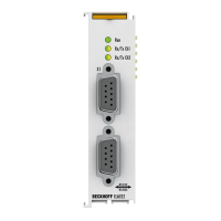
4.7 EtherCAT cabling – wire-bound
The cable length between two EtherCAT devices must not exceed 100 m. This results from the FastEthernet
technology, which, above all for reasons of signal attenuation over the length of the cable, allows a maximum
link length of 5 + 90 + 5 m if cables with appropriate properties are used. See also the Design
recommendations for the infrastructure for EtherCAT/Ethernet.
Cables and connectors
For connecting EtherCAT devices only Ethernet connections (cables + plugs) that meet the requirements of
at least category 5 (CAt5) according to EN 50173 or ISO/IEC 11801 should be used. EtherCAT uses 4 wires
for signal transfer.
EtherCAT uses RJ45 plug connectors, for example. The pin assignment is compatible with the Ethernet
standard (ISO/IEC 8802-3).
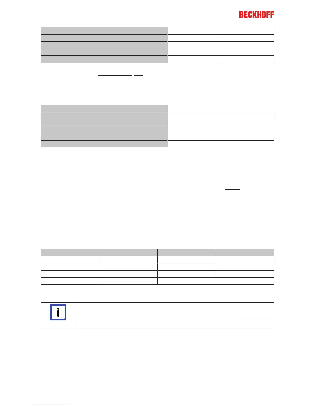
Pin Color of conductor Signal Description
1 yellow TD + Transmission Data +
2 orange TD - Transmission Data -
3 white RD + Receiver Data +
6 blue RD - Receiver Data -
Due to automatic cable detection (auto-crossing) symmetric (1:1) or cross-over cables can be used between
EtherCAT devices from Beckhoff.
Note
Recommended cables
Suitable cables for the connection of EtherCAT devices can be found on the Beckhoff web-
site!
E-Bus supply
A bus coupler can supply the EL terminals attached to it with the E-bus system voltage of 5V; a coupler
usually has a load capacity of up to 2 A in this situation (see documentation for the respective devices).
Information on how much current each EL terminal requires from the E-bus supply is available online and in
the catalogue. If the added terminals require more current than the coupler can supply, then power feed
terminals (e.g. EL9400) must be inserted at appropriate places in the terminal strand.
 Loading...