Access from the user program
KL6031/KS6031, KL6041/KS6041 41Version: 2.1.0
Bit 15 … 15 Bit 4 Bit 3 Bit 2 Bit 1 Bit 0 Data bytes
reserved 1 0 1 1 1 22bytes + 1 Control/Status word in the extended
process data image (see R34.7 [}39])
reserved 0 0 1 1 0 5 bytes + 1 Control/Status byte
reserved 0 0 0 1 1 3 bytes + 1 Control/Status byte
R36 - 63: reserved
5.4 Mapping
The Bus Terminals occupy addresses within the process image of the controller. The assignment of process
data (input and output data) and parameterization data (control and status bytes) to the control addresses is
called mapping. The type of mapping depends on:
• the fieldbus system used
• the terminal type
• the parameterization of the Bus Coupler (conditions), such as
- compact or complex evaluation
- Intel or Motorola format
- word alignment activated or deactivated
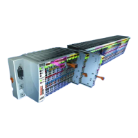
The Bus Couplers (BKxxxx, LCxxxx) and Bus TerminalControllers (BCxxxx, BXxxxx) are supplied with
certain default settings. The default setting can be changed with the KS2000 configuration software or with a
master configuration software (e.g. TwinCAT System Manager or ComProfibus).
The following tables show the mapping depending on different conditions.
Complex evaluation
In the case of complex evaluation, the serial interface terminals occupy addresses in the input and output
process image. Control and Status words can be accessed.
22-byte process image
Complex evaluation in Intel format
Address Input data Output data
Conditions Word offset High byte Low byte High byte Low byte
Complex evaluation: yes
Motorola format: no
Word alignment: any
0 SW CW
1 DataIn1 DataIn0 DataOut1 DataOut0
2 DataIn3 DataIn2 DataOut3 DataOut2
3 DataIn5 DataIn4 DataOut5 DataOut4
4 DataIn7 DataIn6 DataOut7 DataOut6
5 DataIn9 DataIn8 DataOut9 DataOut8
6 DataIn11 DataIn10 DataOut11 DataOut10
7 DataIn13 DataIn12 DataOut13 DataOut12
8 DataIn15 DataIn14 DataOut15 DataOut14
9 DataIn17 DataIn16 DataOut17 DataOut16
10 DataIn19 DataIn18 DataOut19 DataOut18
11 DataIn21 DataIn20 DataOut21 DataOut20
 Loading...