29
EN
table 2
CO2 min
METHANE GAS
(G20)
LPG
(G31)
25C 9,0 10,0 %
30C
9,0 10,0 %
Make sure the ue gas temperature value, read in info I008 (see “5.3
INFO menu ”), is coherent (with a tolerance ± 5°C) with the value
measured by the analyser.
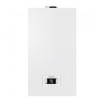
After completing the check:
quit the function by pressing
056
.
rpm
reposition the previously removed components
set the boiler to the required operating mode, depending on the
season
regulate the heat request temperature values according to the custo-
mer’s needs.
b
When the combustion analysis function is active, all heat requests
are inhibited and the message “CO” appears on the display.
IMPORTANT
The combustion analysis function is active for max. 15 minutes; the bur-
ner shuts down if a delivery temperature of 95°C is reached. It will ignite
again when the temperature falls below 75°C.
b
The combustion analysis function is usually carried out with the
3-way valve on heating. The 3-way valve can be switched to DHW
by generating a DHW request at the maximum output while the
function itself is still active. In this case, the DHW temperature will
be limited to a maximum value of 65°C. Wait for the burner to fire
.
4.9 Adjustments
The boiler has already been adjusted by the manufacturer. If the adjust-
ments need to be made again however e.g. following extraordinary
maintenance, after the replacement of the gas valve, after conversion
from methane gas to LPG or vice versa, or after a new regulation for
inside-chimney pipes, follow the procedures described below.
The adjustment of the maximum and minimum output, maximum heating
and slow ignition must be made in the sequence indicated, and by qua-
lified personnel only:
power up the boiler
set the parameters
306 minimum fan speed
307 maximum fan speed
308 slow ignition
309 maximum fan speed for heating
313 ignition speed in restart
table 3
MAX. NO. FAN
ROTATIONS
METHANE GAS
(G20)
LPG
(G31)
25C: CH - DHW 7.000 - 8.700 6.900 - 8.500 rpm
30C: CH - DHW 6.900 - 8.300 6.800 - 7.900 rpm
4.10
table 4
MIN. NO. FAN
ROTATIONS
METHANE GAS
(G20)
LPG
(G31)
25C
1.500 2.050 rpm
30C
1.500 1.700 rpm
table 5
NO. FAN ROTATIONS
SLOW IGNITION
METHANE GAS
(G20)
LPG
(G31)
25C - 30C 5.500 5.500 rpm
Gas valve calibration
Run the CO2 check procedure as explained in paragraph
“4.8
Combustion analysis”.
If the values need to be modified, proceed as
follows
:
check the CO2 adjustment values with the casing closed
remove the casing as explained in paragraph “3.7 Removing the casing”
check the CO2 adjustment values again, with the casing open
on the basis of the difference in values with the casing closed and
open, if necessary bring the CO2 to the value shown in the table (1
and 2) - (minus) the difference found. Example
:
CO2 value measured with the casing closed
= 8,5%
CO2 value measured with the casing open
= 8,3%
value to be set for CO2 with the casing open
= 8,8%
value to be set for CO2 with the casing closed
= 9,0%
to adjust the CO2 value
:
rotate the max. power adjustment screw clockwise to reduce the
value, or anti-clockwise to increase it
rotate the min. power adjustment screw clockwise to increase the
value, or anti-clockwise to reduce it
with the casing open and after adjusting the CO2 value at the mini-
mum power, check the adjustment of the CO2 at the maximum power
again
after completing the adjustments, replace the casing and check the
CO2 corresponds to the value shown in the table 1 and 2
.
CO2 -
CO
2 +
Minimum output
adjustment
screw
Maximum output
adjustment screw
4.11 Gas conversion
Conversion from the gas of one family to the gas of another family can be
done easily even when the boiler is already installed.
This operation must be carried out by professionally qualified personnel.
The boiler is designed to operate with methane gas (G20) or LPG (G31)
according to the product label. The boiler can be transformed to LPG or
to methane gas (G20) by means of special kits.
For disassembly refer to instructions below:
disconnect the boiler from the electricity supply and turn off the gas tap
remove the casing as explained in paragraph “3.7 Removing the casing”
release the instrument panel and rotate it forwards
unscrew the ramp nut from the gas valve and rotate the ramp so as to
have access to the gas nozzle (B) in the outlet fitting
remove the nozzle (B) and replace it with the one from the kit
put the ramp of the gas valve back in place and screw the nut
reposition the previously removed components
power up the boiler and open the gas tap again.
Adjust the boiler as explained in paragraphs “4.9 Adjustments” and “4.10
Gas valve calibration”.
b
Conversion must be carried out by qualified personnel
b
After the transformation, apply the new gas rating plate inclu-
ded in the kit.
b
After each intervention on the adjustment element of the gas
valve, seal it with sealing varnish.
4.12 Range rated
This boiler can be adapted to the heating requirements of the system,
in fact it is possible to set the maximum delivery for heating operation of
the boiler itself:
power up the boiler
set the parameter
310 Range rated
Set the maximum heating value (rpm) and confirm.
confirm
MAX
rpm
007
.
rpm
007
.
rpm
Record the new set value in the table on the back cover of this manual.
For subsequent controls and adjustments, refer to the set value.
b
The calibration does not entail the ignition of the boiler.
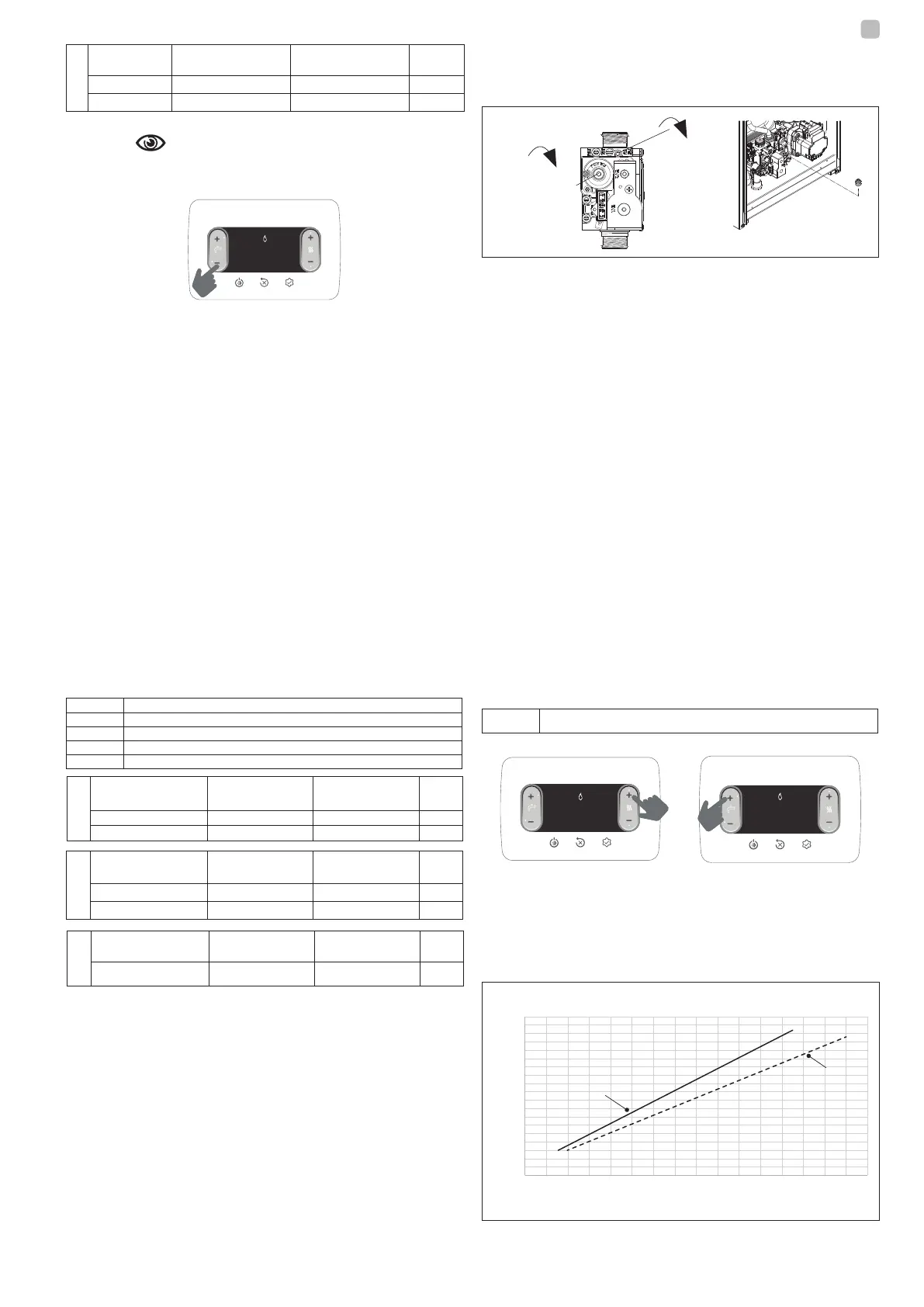
The boiler is supplied with the adjustments shown in the technical data
table. Depending on plant engineering requirements or regional flue gas
emission limits however, this value can be modified by referring to the
graph below.
0
500
1000
1500
2000
2500
3000
3500
4000
4500
5000
5500
6000
6500
7000
7500
8000
8500
9000
9500
0 2 4 6 8 10 12 14 16 18 20 22 24 26 28 30 32
25C
30C
Fan rotation (r.p.m.)
Heat input (kW)
Heat input curve - fan rotation
 Loading...