40
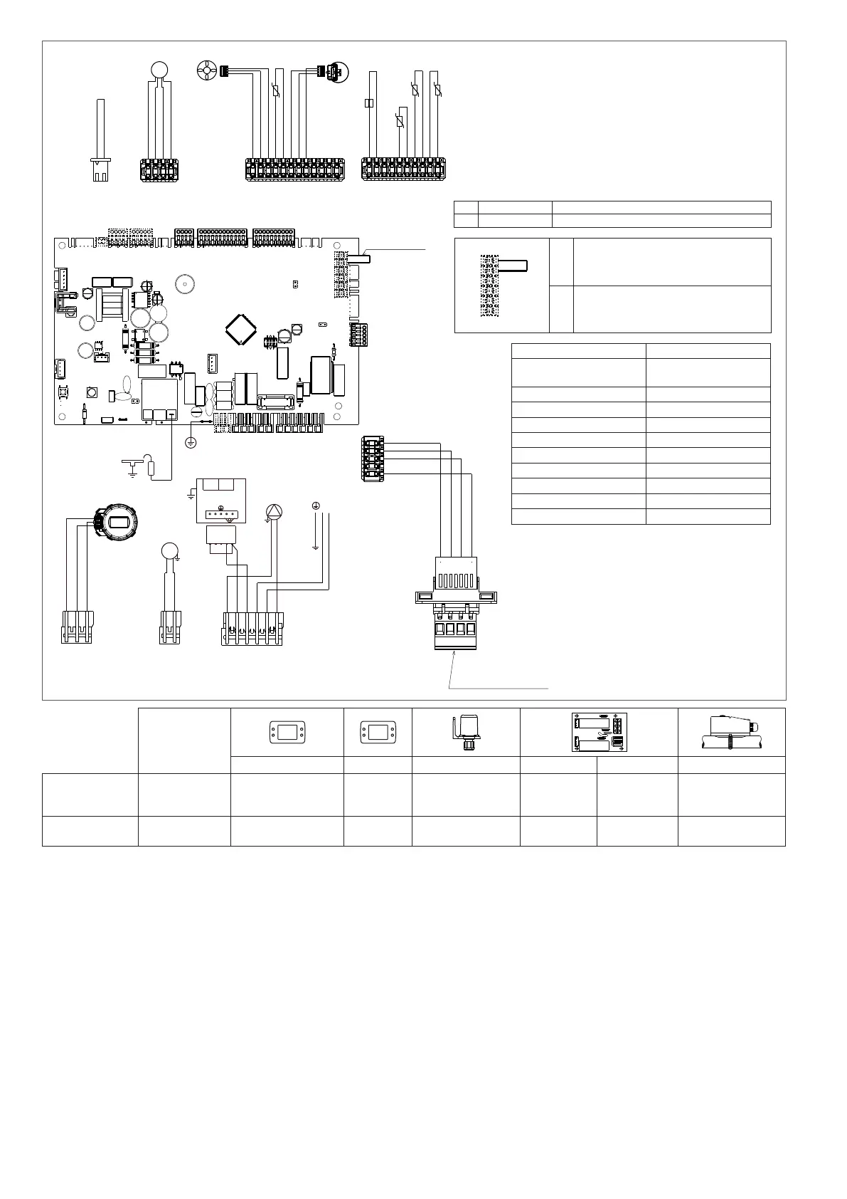
8.5 Schema elettrico multilare
AKJL01: Scheda comando
X1-X25: Connettori di collegamento
ACC1: Trasformatore di accensione
E.A./R.: Elettrodo accensione/rilevazione
F: Fusibile 4A T
3V: Servomotore valvola 3 vie
V Hv: Alimentazione ventilatore 230 V
OPE: Operatore valvola gas
P: Pompa
CE4: Connettore colleg. esterni: (- A B +) Bus 485
S.R.: Sonda ritorno temperatura circuito primario
S.M.: Sonda mandata temperatura circuito primario
S.F.: Sonda fumi
T.L.A.: Termostato limite acqua
T.P.: Trasduttore di pressione
S.S.: Sonda ritorno temperatura circuito sanitario
F.S.: Flussimetro sanitario
V Lv: Segnale controllo ventilatore
T.B.T.: Termostato bassa temperatura
Per effettuare il collegamento del:
TBT = termostato bassa temperatura occorrre tagliare a metà il ponticello colore
bianco marcato con la scritta TBT presente nel connettore 2 poli (X25),
spellare i li e utilizzare un morsetto elettrico per la giunzione.
8.5 Multiwire wiring diagram
AKJL01: Control board
X1-X25: Connection connectors
ACC1: gnition transformer
E.A./R.: Ignition/detection electrode
F: Fuse 4A T
3V: 3-way valve servomotor
V Hv: Fan power supply 230 V
OPE: Gas valve operator
P: Pump
CE4: Connector for ext. connections: (- A B +) Bus 485
S.R.: Temperature return sensor on primary circuit
S.M.: Temperature ow sensor on primary circuit
S.F.: Flue gas sensor
T.L.A.: Water limit thermostat
T.P.: Pressure transducer
S.S.: DHW circuit temperature return sensor
F.S.: Flow meter
V Lv: Fan control signal
T.B.T.: Low temperature limit thermostat
To connect the:
T.B.T. = low temperature thermostat it is necessary to cut in half the white jumper
marked with the word TBT present in the 2-pole connector (X25), strip the
wires and use an electric terminal for the junction.
IT
Valvola gas CE4: (connettore estraibile posizionato sotto mensola)
EN
Gas valve CE4: (removable connector positioned under shelf)
marrone
blu
2
1
3
5
4
VALVOLA GAS
1 2 43
OPEOPE
rosa
blu
P
marrone
N
L
230 V
blu
blu
marrone
marrone
marrone
blu
marrone
X5
blu
V Hv
1
2
rosso (alim.) +24Vdc
blu (HS)
rosa (PWM)
grigio (-)
X13
V Lv
1
4
1
10
X19
-t°
-t°
-t°
T.L.A.
S.R.
S.M.
S.F.
rosso
rosso
bianco
bianco
grigio
grigio
blu
blu
1
X9
12
rosso
nero (alim.) +5Vdc
blu (sign.)
marrone (-)
S.S.
1
3
TP
rosso
-t°
grgio (-)
blu (sign.)
FS.
1
3
rosa (alim.) +5Vdc
1
2
bianco
X25
TBT
nero (-)
arancione (A)
giallo (B)
rosso (+24 Vdc)
-
A
B
+
CE4 (connettore estraibile
posizionato sotto mensola)
5
1
rosso (+24 Vdc)
giallo (B)
arancione (A)
nero (-)
X14
3
1
X4
nero (sanit.)
marrone (risc.)
blu (N)
3V
X1
X5
X4
X6
X14
X11
X19X9
X13
X21
X2
X25
ACC1
X3
F=4A T
1
10
1
12
14
5
1
14
1
5
Elettrodo
A/R
TA
OT+
SE
AKJL01 GAR
Utilizzare contatto
privo di tensione
6
1
X1
IT EN
NOTA: LA POLARIZZAZIONE
L-N È CONSIGLIATA
“L-N” CONNECTION IS
ADVISABLE
Blu Blue
Marrone Brown
Nero Black
Rosso Red
Bianco White
Rosa Pink
Arancione Orange
Grigio Grey
Giallo Yellow
X6
X11 X11 X11 X2 X21 X25
IT - ACCESSORI
L-N
resistenze antigelo
TA: termostato ambiente OT+ SE: (sonda esterna)
Remotazione
allarme
Valvola di zona o
pompa supple-
mentare
TBT: Termostato bassa
temperatura
EN - ACCESSORIES
L-N
antifreeze heaters
TA: room thermostat OT+
SE: (outdoor
temperature sensor)
Alarm remote
control
Zone valve or
additional pump
TBT: Low temperature
limit thermostat
X11
TA
IT
TA: (utilizzare contatto privo di tensione)
Il collegamento del termostato ambiente deve
essere effettuato sul connettore a vite X11 dopo
aver rimosso il ponticello.
EN
Room thermostat: (voltage free contact input)
The connection of the room thermostat must be
made on the screw connector X11 after removing
the jumper.
 Loading...