9
ENGLISH
b
The minimum permissible pressure difference between the flue gas outlet and the
combustion air inlet is -200 Pa (including - 100 Pa of wind pressure).
For both types of exhaust, further accessories are available (curves, extensions, terminals,
etc.) which make possible the ue gas exhaust congurations foreseen in the boiler booklet.
b
The pipes must be installed in such a way as to avoid condensation sticking which
would prevent the correct evacuation of the combustion products.
b
A data plate must be present at the connection point with the collective flue pipe. The
plate must include at least the following information:
- the collective ue is sized for boilers C(10) type
- the maximum permissible mass ow of the combustion products in kg/h
- the dimensions of the connection to the common pipes
- a warning concerning the openings for the air outlet and the entry of the combu-
stion products of the collective pressure pipe; these openings must be closed and
their tightness must be checked when the boiler is disconnected
- the name of the manufacturer of the collective smoke pipe or its identication
symbol.
b
See applicable legislation for the discharge of the combustion products as well as
local regulations.
b
The flue gas pipe must be suitably selected based on the parameters shown below.
maximum length minimum length UM
ø 60-100 4,5 0,5 m
ø 80 4,5 0,5 m
ø 80/125 4,5 0,5 m
b
The terminal of the collective pipe must generate an upward air current.
b
Before attempting any operation, disconnect the appliance from the electrical supply.
b
Before assembling, lubricate the gaskets with a non-corrosive glide lubricant.
b
The flue gases discharge pipe should be inclined, if the pipe is horizontal, by 3°
towards the boiler.
b
The number and characteristics of the exhaust ventilation devices which are the real
characteristics of the flue itself.
b
The condensation can flow inside the boiler.
b
The maximum recirculated value allowed in wind conditions is 10%.
b
The maximum permissible pressure difference (25 Pa) between the combustion
products inlet and the air outlet of a collective flue can not be exceeded when-
1 boiler work at the maximum nominal heat output and 1 boiler within minimum
temperature allowed by the checks.
b
The collective smoke pipe must be adequate for an overpressure of at least 200 Pa.
b
The collective flue must not be equipped with a wind-proofing device.
At this point it is possible to install the curves and extensions, available as accessories,
depending on the type of installation desired.
The maximum permissible lengths of the ue pipe and the air intake pipe are given in the
instruction manual of the reference device (g 18a-18b).
With C(10) installation, in any case, report the number of fan speed (rpm) on the
label placed next to the data plate.
Installation currently not available on model 40kW.
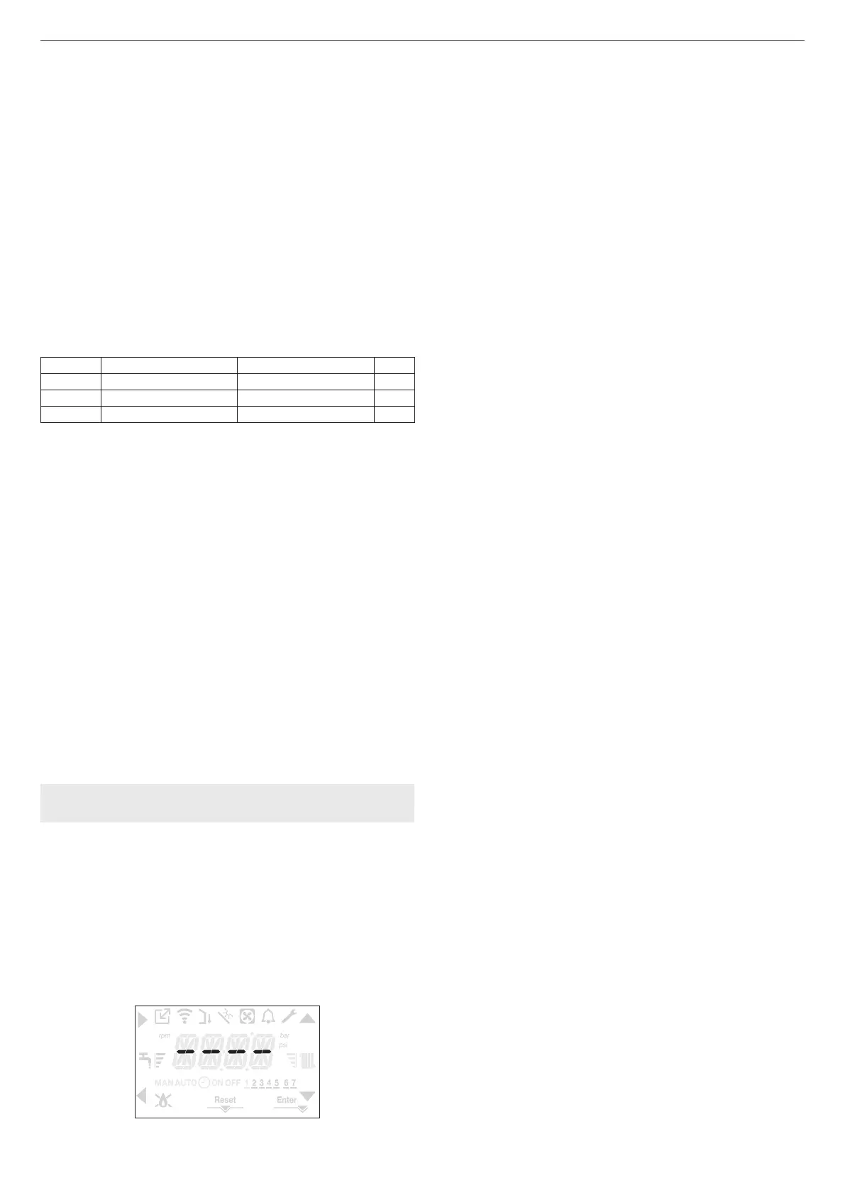
3.16 Filling the heating system and eliminating air
Note: the rst lling operation must be carried out by turning the lling tap (external to the
boiler) with the boiler OFF.
Note: each time the boiler is powered up, the automatic venting cycle is carried out.
Note: the presence of a water alarm (40, 41 or 42) does not allow the venting cycle to be
carried out. The presence of a domestic hot water request during the venting cycle interrupts
the venting cycle.
Once the hydraulic connections have been made, ll the heating system as follows:
- set the boiler to OFF by pressing button 1
- Open the plug of the air vent valve (A - g. 19) by two or three turns to allow the
continuous bleeding of the air, and leave the valve cap (A - g. 19) open.
- Connect the supplied silicone pipe to the de-aeration tap (D - g. 19) and take a bucket
to collect any water that may come out after bleeding.
- Open the de-aeration tap (D - g. 19).
- Turn on the lling tap (external to the boiler).
- Wait until the water comes out continuously from the de-aeration tap (D - g. 19), then
close it.
- Wait for the pressure to increase: check that it reaches 1-1.5 bar; then close the system
lling tap (external to the boiler).
Note: if the mains pressure is less than 1 bar, keep the system lling tap (external to the
boiler) open during the venting cycle and close it once it has nished.
- To start the vent cycle shut off the electrical power for a few seconds; connect the power
again leaving the boiler OFF. Check that the gas tap is closed.
- At the end of the cycle, if the circuit pressure has dropped, open the lling tap (external
to the boiler) again to bring the pressure back up to recommended levels (1-1.5 bar).
The boiler is ready after the vent cycle.
- Remove any air in the domestic system (radiators, zone manifolds, etc.) using the bleed
valves.
- Once again check that the system pressure is correct (ideally 1-1.5bar) and restore the
levels if necessary.
- If air is noticed when operating, repeat the vent cycle.
- Once the operations are nished, open the gas tap and ignite the boiler.
At this point it is possible to carry out any heat request.
3.17 Draining the heating system
Before draining, set the boiler to OFF and shut off the electrical supply setting the system's
main switch to “off”.
- Close the heating system's taps (if present).
- Connect a pipe to the system discharge valve (C - g. 19), then manually loosen it to let
the water ow out.
- Once the operations have been completed, remove the pipe from the system discharge
valve (C - g. 19) and close it again.
3.18 Condensate siphon
When the boiler is rst started the siphon for collecting the condensate is empty.
When eliminating air from the boiler, the siphon lls.
- Slowly open the de-aeration tap (A - g. 19) and leave it open until the amount of water
contained in the siphon reaches the ledge.
- Close the de-aeration tap (A- g. 19)
- Check that there are no leaks from the SRD device connection zone and that the device
allows the liquid to run off correctly.
- Check that the system pressure has not dropped below 1 bar. If necessary, ll the system.
Repeat this operation during maintenance work.
CHECK THAT THE CONDENSATE DRAIN OUTLET SIPHON CONTAINS WATER, IF IT
WAS NOT FILLED PROCEED AS DESCRIBED ABOVE.
 Loading...