7
3 ACTUATOR INSTALLATION
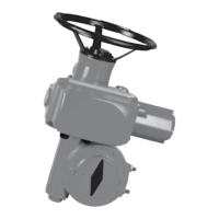
3.1 Fastening actuator on the valve
Actuator should be secured directly to the
valve using proper bolts or via a proper
interface.
After assembly, the actuator can operate in
any position.
You can modify your display orientation
to keep normal reading orientation.
To set display orientation, see §5.6.
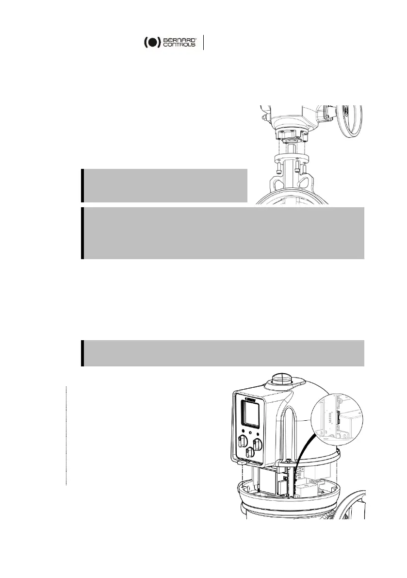
3.2 Opening the control compartment
You need to open the control compartment and remove the cover in
order to wire the actuator.
If closing direction is not standard (clockwise), and it is not already
done, change the orientation of the position indicator cap.
How to remove the cover
1. With 10mm angled socket
wrench or flat blade
screwdriver, unscrew the 4
screws from the housing.
2. Raise the cover along its axis.
3. When cover plug is accessible,
unplug it from the mainboard
4. Remove the cover completely.
However:
do not handle the actuator by handwheel to avoid damage on
actuator gearing
cable glands must not be oriented upwards (loss of water
tightness)
When opening, unplug the control panel cable from the main board in
order to avoid to damage it.
 Loading...