16
5.5 Calibration of position feedback (OPTION)
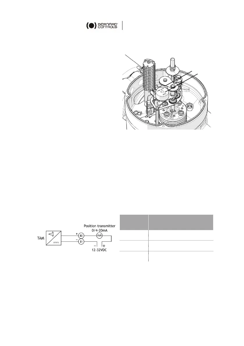
Position feedback board
Two components can be used
for position feedback:
• a potentiometer (1).
• a “TAM” (2), which gives
position feedback from a
4-20 mA signal.
The potentiometer can be used
alone (Positioner) or can be
combined with the TAM
(Position transmitter).
Position transmitter (OPTION)
The position transmitter delivers a 4 to 20 mA signal that is linearly
proportional to the opening percentage of the valve.
Electrical connections
To connect the TAM, please refer to the supplied wiring diagram.
A filtered or stabilized power supply should be provided within the
12 to 32 VDC range. The maximum admissible resistances for the
wiring are indicated in the following table:

 Loading...