2 3
Internal wiring diagrams and examples of power supply circuits Page 3
Control panel design examples Page 4
1 Safety information Page 5
2 Assembly Page 5
3 Handwhee loperation and declutching Page 5
4 Electrical connections and preliminary tests Page 5
5 Setting of travel limit switches Page 6
6 Torque limiter Page 6
7 Proportional optical indicator Page 7
8 Position feedback potentiometer (option) Page 7
9 «TAM» position transmitter (option) Page 7
10 Precautions Page 8
11 Maintenance and storage instructions Page 9
BERNARD CONTROLS international network Page 20
TABLE OF CONTENtS
Schémas de cablage interne et exemples de circuits de puissance Page 3
Exemples de réalisation de coffrets de commande Page 4
1 Sécurité Page 10
2 Montage Page 10
3 Commande manuelle et debrayage Page 10
4 Raccordement et tests electriques Page 10
5 Réglage des contacts de fin de course Page 11
6 Limiteur de couple Page 11
7 Indicateur de position optique Page 12
8 Potentiometre de recopie de position (option) Page 12
9 Transmetteur de position type tam (option) Page 12
10 Précautions Page 13
11 Entretien et stockage des servomoteurs Page 14
Le reseau international BERNARD CONTROLS Page 20
SOMMAIRE
Interne verdrahtung und schaltungsbeispiele stromversorgung Seite 3
Schaltungsbeispiele steuerung Seite 4
1 Sicherheits- und warnhinweise Seite 15
2 Montage Seite 15
3 Handradbetâtitung und auskupplung Seite 15
4 Elektroanschlusse und deren uberprufung Seite 15
5 Einstellung der wegendschalter Seite 16
6 Einstellung der drehmomentschalter Seite 17
7 Optische stellungsanzeige Seite 17
8 Potentiometer zur positionsdruckmeldung (option) . Seite 17
9 Stellungsgeber, typ «tam» (option) Seite 18
10 Vorsichtsmassnahmen Seite 19
11 Wartung und instandhaltung der servomotoren Seite 19
BERNARD CONTROLS - internationale Seite 20
INHALTSVERZEICHNIS
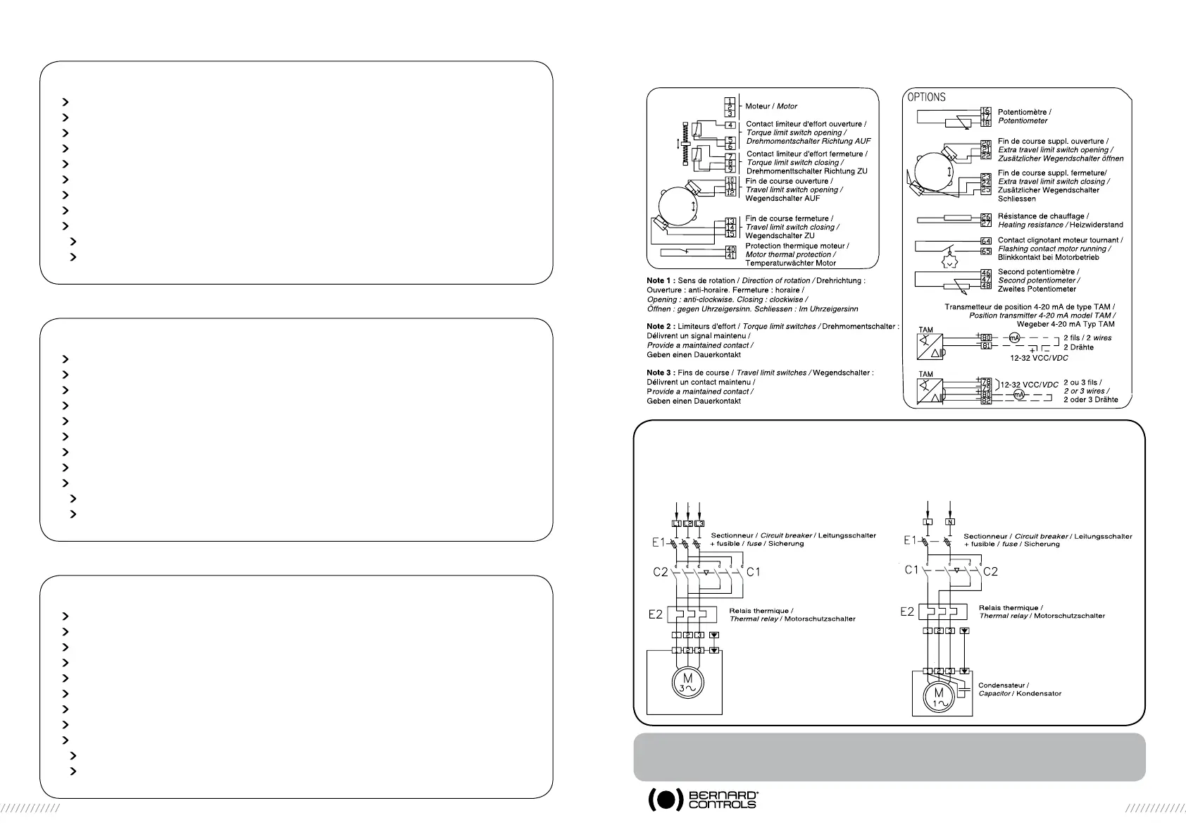
SCHEMAS DE CABLAGE INTERNE - EXEMPLES DE CIRCUITS DE PUISSANCE
INTERNAL WIRING DIAGRAMS - EXAMPLES OF POWER SUPPLY WIRING
INTERNE VERDRAHTUNG - SCHALTUNGSBEISPIELE STROMVERSORGUNG
Autres versions (VCC par ex.) : nous consulter /
Other versions (VDC i.e): please consult us /
Andere Ausführungen (z.B. Gleichspannung) : Nehmen SIe Rücksparache mit uns !
3 PHASES 1 PHASE
Légende : C1 = contacteur ouverture ; C2 = contacteur fermeture
Legend: C1 = opening contactor ; C2 = closing contactor
Legende : C1 = Schütz Öffnen ; C2 = Schütz Schliessen
 Loading...