(Fig. 7)
(Fig. 8)
14 15
Setting of potentiometer zero is achieved thanks to the «0% postion» screw.
Drive the actuator to the closed position.
Resistance value is measured between terminals 16 and 17.
Hold the pinion located just under the plate with the «0% position»
marking while driving the potentiometer screw. Adjust the potentiometer
so that the resistance value exceeds 0 Ohm and regularly increases then
turn backwards to reach a value as close to 0 Ohm as possible.
Mettre le servomoteur en position ouverte et noter la valeur de résistance
pour le 100%. Revenir en position fermée et vérifier que la valeur du 0%
est bien répétable et proche de 0 Ohm.
Drive the actuator to the open position and write down the resistance
value corresponding to the 100% position.
Come back to the closed position and check that, for the 0% position,
the resistance shows a close to zero repeatable value.
Note: If actuator is equipped with 2 potentiometers, each potentiometer is
set independently of the other.
Signal inversion:
To inverse the signal variation direction, invert potentiometer wires
on the actuator terminal board (e.g. for a connection on 16/17/18, invert
16 and 18).
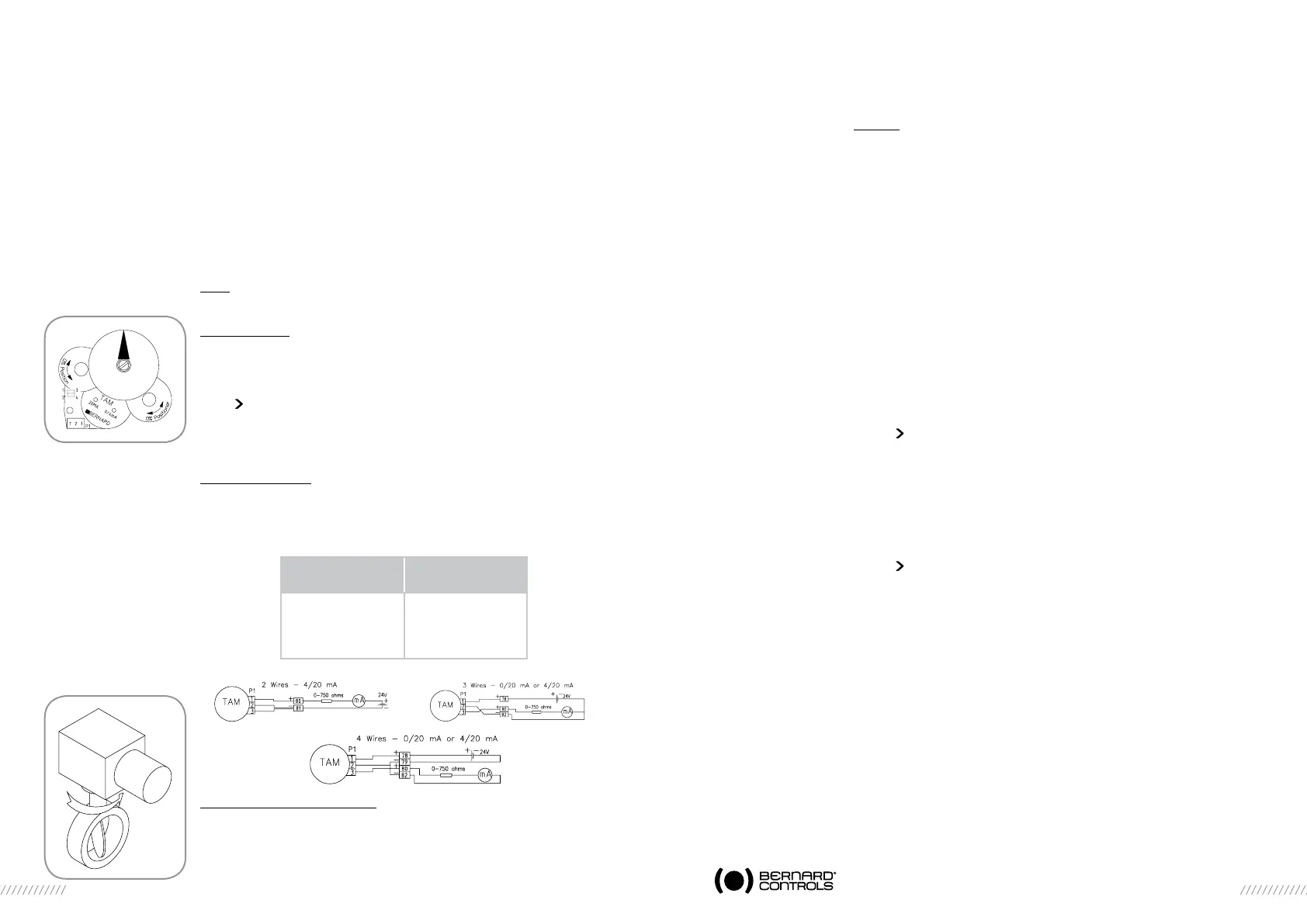
9 «TAM» FEEDBACK POSITION TRANSMITTER (OPTION - Fig.7)
The TAM transmitter delivers a 0/4 to 20 mA signal linearly proportional
to the valve position.
Electric connections
Refer to the actuator standard wiring diagram. See also some typical
wiring examples below. FIltered or stabilised power supply should be provided
within the 12 to 32 VDC range. Maximum admissible ohmic load values
are given in the table :
Signal direction inversion (Fig.8)
The TAM transmitter, when supplied with a standard actuator, provides
a signal that rise from close position to open position, the standard opening
direction being counter-clockwise.
If an opposite signal variation is required, simply move 2 jumpers on the board
near the potentiometer.
Direct signal: jumpers on 1-3 and 2-4
Reversed signal: jumpers on 1-2 and 3-4
Settings
Connect a milliampermeter at the place of burden.
- Always start by adjusting the 0/4mA.
- Drive actuator to the position corresponding to the 0/4 mA (closed
in standard),
- Hold the pinion located just under the plate with the «0% position»
marking while driving the potentiometer screw. Adjust the potentiometer
so that the output current reaches a minimum value. Turn backwards
until the current value regularly increases then turn backwards again
and stop as soon as the minimum value determined here above
has been reached. The potentiometer is then positioned at the very
beginning of its track.
- Then, use the TAM adjustment screw marked as «0/4mA» to adjust
the current to a value as close to the 0/4 mA as possible.
- Drive actuator to the position corresponding to the 20 mA (open
in standard),
- Turn the screw marked «20mA» in order to read exactly 20 mA
on the milliampermeter.
- Come back to the closed position and check that, for the 0% position,
the signal current shows a close to 0/4 mA and repeatable value.
10 PRÉCAUTIONS
Close the cover immediately after start-up and make sure that the cover
seals are not damaged and remain clean.
It is important to ensure a proper protection covers closing in order
to avoid any water entry.
In case of water entry, dry thoroughly and check electric insulation before
replacing covers.
11 MAINTENANCE AND STORAGE INSTRUCTIONS
Maintenance
All ST actuators are lubricated for lifetime and therefore require no specific
maintenance.
The condition of the valve stem and its nut must nevertheless be checked
periodically to make sure they are clean and well lubricated.
We recommend that a program of periodic maintenance should be drawn
up for actuators that are operated unfrequently.
Storage
The actuator includes electric equipment as well as grease lubricated gear
stages. In spite of the weatherproof enclosure, oxidation, jamming and
other alterations are possible if actuator is not correctly stored.
The actuators should therefore be stored under a shelter in a clean, dry
place and protected from wide changes in temperature.
Avoid placing the actuators directly on the floor. For the actuators equip-
ped with a heating resistance, it is recommended that to connect and
power supply it especially if the storage area is humid (standard voltage
230 volts, unless otherwise specified).
Power Supply DC
(VOLT)
Max. admissible
load Ohm
12 150
34 750
30 1050
 Loading...