11
marking while driving the potentiometer screw. Adjust the potentiometer so that the resistance
value exceeds 0 Ohm and regularly increases then turn backwards to reach a value as close to 0
Ohm as possible.
Drive the actuator to the open position and write down the resistance value corresponding to the
100% position.
Come back to the closed position and check that, for the 0% position, the resistance shows a close
to zero repeatable value.
Note: If actuator is equipped with 2 potentiometers, each potentiometer is set independently of
the other.
Signal inversion:
To inverse the signal variation direction, invert potentiometer wires on the actuator terminal board
(e.g. for a connection on 16/17/18, invert 16 and 18).
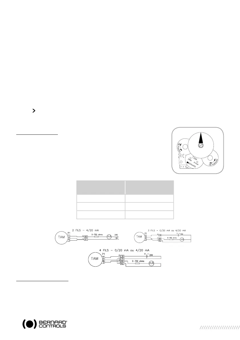
11 “TAM” POSITION FEEDBACK TRANSMITTER (OPTION)
The TAM transmitter delivers a 0/4 to 20 mA signal linearly proportional to the position of the valve.
Electric connections
Refer to the wiring diagram supplied with the actuator.See also some
typical wiring examples below.
Filtered or stabilised power supply should be provided within the 12 to
32 VDC range.
Maximum admissible ohmic load values are given in the table :
Signal direction inversion
The TAM transmitter, when supplied with a standard actuator, provides a signal that rise from close
position to open position, the standard opening direction being counter-clockwise.
If an opposite signal variation is required, simply move 2 jumpers on the board near the potentio-
meter.
Direct signal: jumpers on 1-3 and 2-4
Reversed signal: jumpers on 1-2 and 3-4
Energy Supply
DC (VOLT)
Max. admissible load
Ohm
12 150
24 750
30 1050
 Loading...