8
2. If stored for more than one year:
• Long-term storage causes the consistency of the grease to change. To avoid any
grease-drying problem, do some rotations of the actuator several times a year by using
motor or manual override.
• Visual inspection of electrical parts.
4 ACTUATOR ON VALVE ASSEMBLY
Actuator should be secured directly to the valve using proper bolts or via a proper interface.
After assembly, the actuator can operate in any position. However, cable glands should not be
oriented upwards (loss of water tightness) and the motor will preferably not be positioned at the
bottom (potential internal condensation trap)
Note 1: do not lift the actuator by handwheel, it could damage the wormwheel gear.
Note 2: see §.3 for details on storage precaution prior to starting-up.
Note 3: Greasing of A form drive bush trust unit has to be done prior to mounting actuator on valve
(in the case of a rising stem valve).
5 ELECTRICAL CONNECTION
A wiring diagram is normally supplied with the actuator. If
this is not the case, please ask our customer service.
Operating procedure :
a) Check the power supply characteristics with respect to
the rating nameplate.
b) Open the terminal box (fig. 2), connect the power and
control circuits (ring tongue not supplied). The screw dia-
meters is 3mm for the control and 4mm for the power.
Check the wiring.
c) make sure that the cover screws, cable glands are pro-
perly tighten and IP68 waterproofness is assured by an
O ring or by a thread sealant as noticed §1.3.
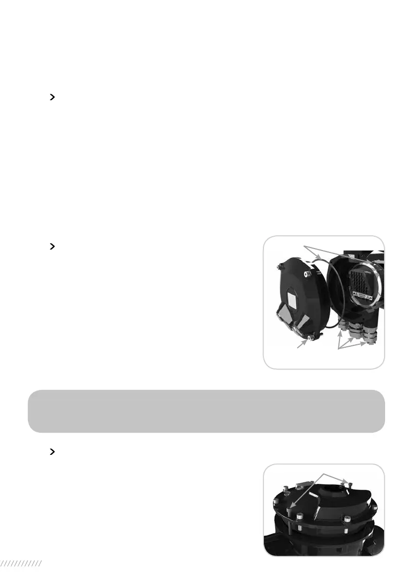
6 PRELIMINARY TESTS
a) Open the front cover. Due to its high level of tightness,
in order to ease the opening, we do recommend to screw
two M8 screws (minimum length 40mm) into the two holes
(cf. fig.3).
b) Move the valve manually to an half-open position,
c) Operate an electrical opening and check that the motor ro-
tates in the right direction. Press manually on the «OPEN»
travel limit switch ; the motor should stop.
WARNING
Torque, travel limit and motor thermal overload switches must be integrated into
your control system (see wiring examples) in order to prevent potential damage
to the actuator or valve.
Cable entries
Captive
screws
(fig. 2)
O-rings
Cover
M8 screws
(fig. 3)
 Loading...