I945P-A7
15
CHAPTER 3: HEADERS & JUMPERS SETUP
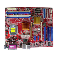
3.1 HOW TO SETUP JUMPERS
The illustration shows how to set up jumpers. When the jumper cap is
placed on pins, the jumper is “close”, if not, that means the jumper is
“open”.
Pin opened Pin closed Pin1-2 closed
3.2 DETAIL SETTINGS
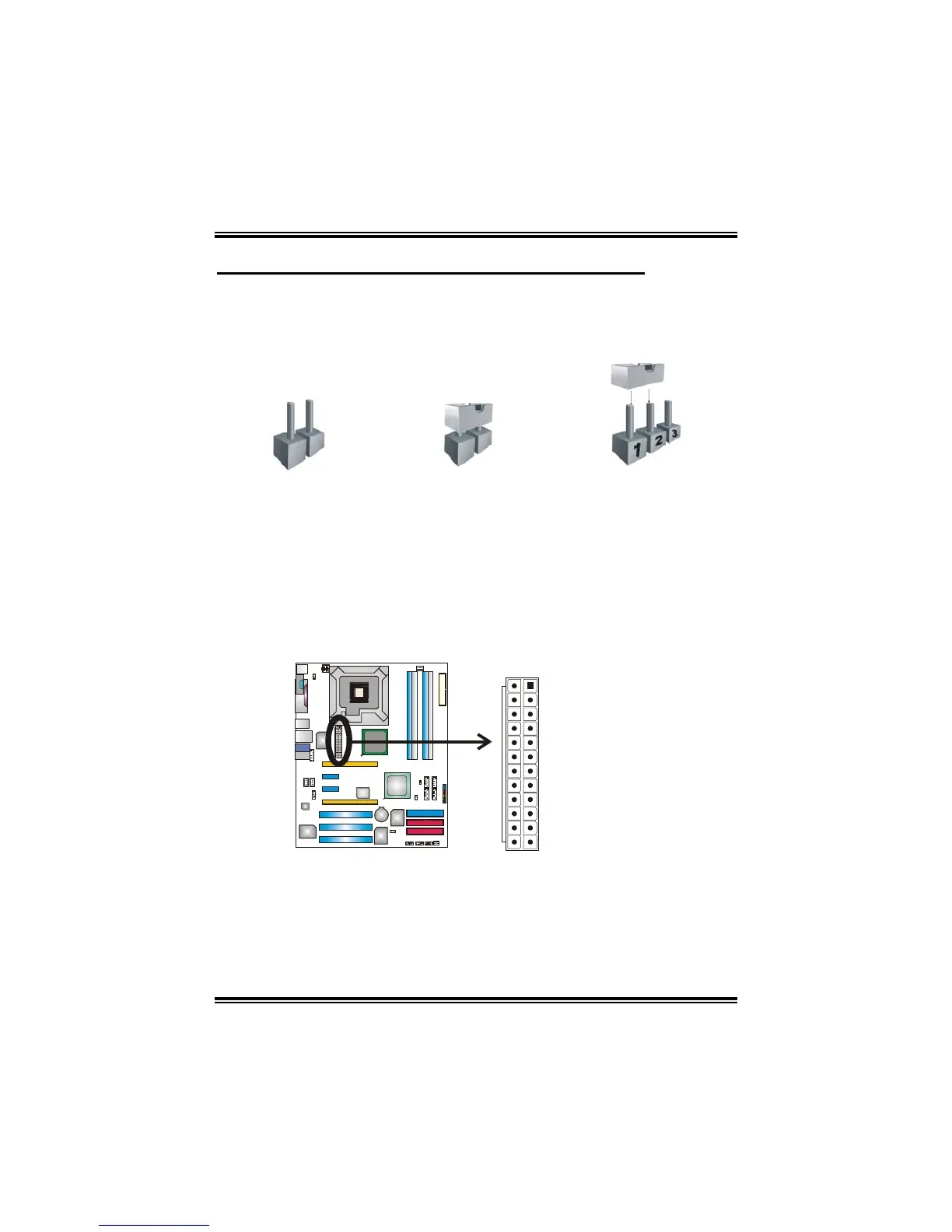
JATXPWR1: ATX Power Connector
This connector allows user to connect 24-pin power connector on the ATX
power supply.
Pin Assignment
1 +3.3V
2 +3.3V
3 Ground
4 +5V
5 Ground
6 +5V
7 Ground
8 PW_OK
9 Standby Voltage
+5V
10 +12V
11 +12V
12 2 x 12 Detect
13 +3.3V
14 -12V
15 Ground
16 PS_ON
17 Ground
18 Ground
19 Ground
20 -5V
21 +5V
22 +5V
23 +5V
13
1
24 12
Code c
C
O
M
1
24 Ground
 Loading...