Page 12
877-877-2269 | BlackBox.com
Chapter 2: Overview
2.4 Hardware Description
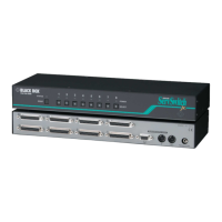
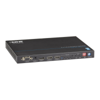
Figures 2-1 and 2-2 show the front and back panels of the switcher. Tables 2-1 and 2-2
describe their components.
1 2 3 4 4 5 6 7 8 9
Figure 2-1. Front panel.
Table 2-1. Front-panel components.
Number in
Figure 2-1
Name Description
1 VGA IN Connects to VGA source device.
2 Audio IN Stereo audio (embedded with VGA inputs).
3 DisplayPort IN Connects to DisplayPort source device.
4 HDMI IN Connects to HDMI source device.
5 Source Selection
LEDs
LED: Lights on if the corresponding source is selected.
6 Source Selection
Button
Selection button: press the button to select source 1
to 4 as input in turn.
7 Sink Selection
Button
On: Turn on the TV by CEC.
Off: Turn off the TV by CEC.
NOTE: Used for TV that supports CEC
8 4-Pin DIP switch Pin 1: Audio De-embedded;
Pin 2: Source Switch;
Pin 3: CEC Control Mode;
Pin 4: Control Mode
9 Scaler Toggles the switch to manage the output scaler.
 Loading...