Panel Descriptions
3
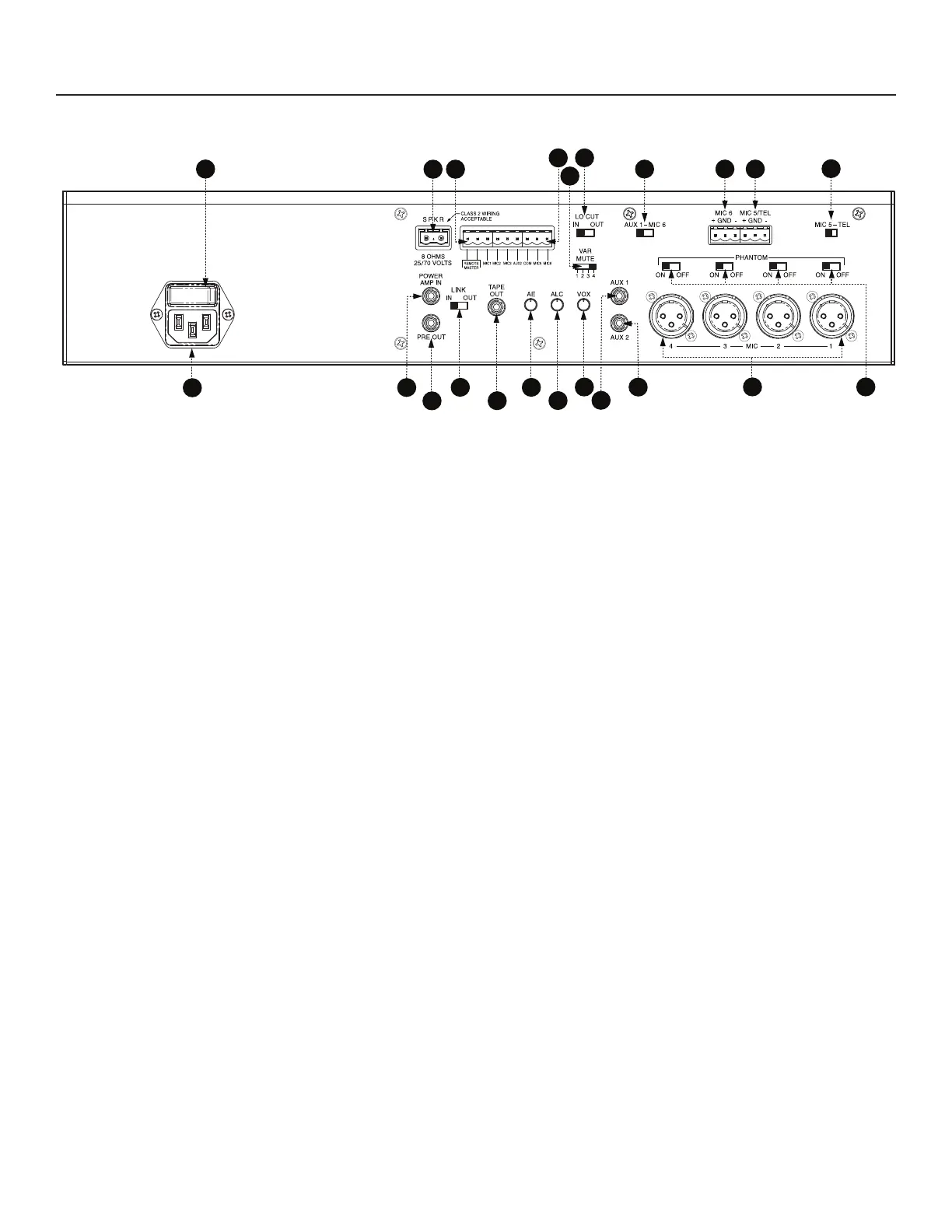
Rear Panel (All Models)
1. IEC Power Input - AC mains connection.
2. POWER Switch - AC power switch.
3. Amplifier Output Speaker Terminals - Pluggable screw terminals connect to speaker loads. Class 2 wiring acceptable.
4. REMOTE MASTER - Pluggable screw terminals pair for connection of remote master volume control (Bogen model
GSRVC).
5. MIC/AUX/TEL PRECEDENCE - Pluggable screw terminal connections that allow externally controlled muting of
individual inputs.
6. VAR MUTE - 4 switch selectable levels of AUX input signal muting during TEL page (works only in the TEL input mode).
7. LO CUT FILTER - Enables or disables low frequency roll off (65 Hz) for all microphone inputs.
8. MIC 6/AUX 1 - Switch selects either MIC 6 or AUX 1 connections as input.
9. MIC 6 - Screw terminals for balanced microphone (active only when AUX 1/MIC 6 switch is set to MIC 6).
10. MIC 5/TEL - Dual-function screw terminals for either balanced microphone or 600-ohm balanced input from
telephone page port.
11. MIC 5/TEL - Switch selects either MIC 5 or TEL connections as input.
12. POWER AMP IN - RCA unbalanced direct input to power amp stage for connection to external signal processing
equipment (used in conjunction with PRE OUT and LINK switch).
13. PRE OUT - RCA unbalanced output from preamp/mixer stage for connection to external signal processing
equipment (used in conjunction with POWER AMP IN and LINK switch).
14. LINK - Switch that makes or breaks the internal connection between preamp/mixer stage and power amp stage
when used with external signal processing equipment.
15. TAPE OUT - RCA unbalanced output, pre-EQ and master volume. (Post Lo-Cut filter, see #7).
16. AE - Variable control for adjusting the amount of Audio Enhancement effect.
17. ALC - Variable control adjusts amount of Automatic Level Control applied to TEL input (works only in TEL input mode).
18. VOX - Variable control adjusts TEL input signal level trigger point for automatic muting of the AUX inputs
(works only in TEL input mode).
19. AUX 1 - RCA unbalanced input for AUX 1 input signal (works only when AUX 1/MIC 6 switch is set to AUX 1).
20. AUX 2 - RCA unbalanced input for dedicated AUX 2 input.
21. MIC 1 to 4 - Balanced XLR connectors for dedicated microphone inputs.
22. PHANTOM (MIC 1 to 4) - Individual switches enable or disable phantom power to each of the 4 dedicated
microphone inputs.
 Loading...