EasyManuals Logo
Home>Bogen>Amplifier>PS240

Bogen PS240 User Manual

Bogen PS240
16 pages
To Next Page IconTo Next Page
To Previous Page IconTo Previous Page
Page #8 background imageLoading...
Page #8 background image
Input Connections
4
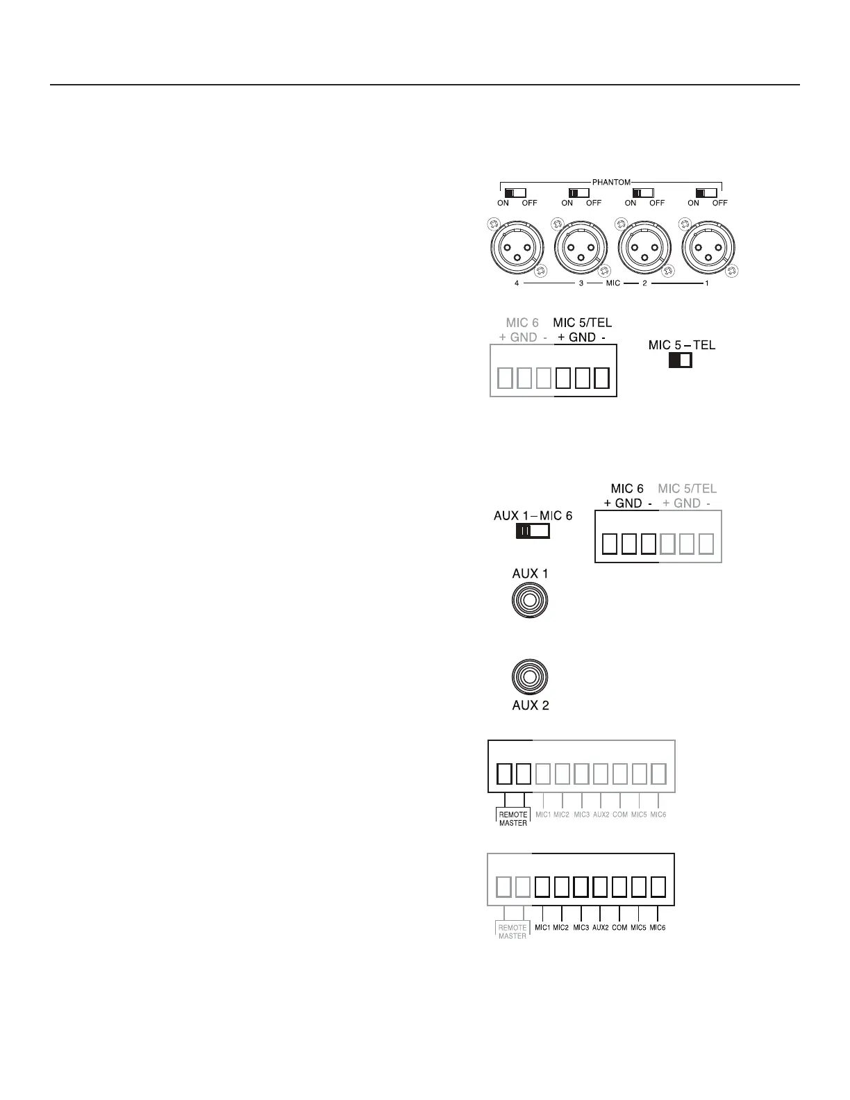
MIC 1- 4 (Rear Panel; #21 and #22)
MIC 1 through 4 utilize female XLR-type microphone connectors. A slide
switch located above each XLR connector is used to supply phantom
power for condenser microphones.
MIC 5/TEL (Rear Panel; #10 and #11)
The MIC 5/TEL input is designed to accept input from a microphone
or from a telephone page port. A slide switch is provided to select MIC 5
or TEL input. To connect a microphone, place the MIC 5/TEL switch in
the MIC position. Use two conductor shielded cable and connect the
cable shield to the center GND terminal. To use the TEL input, place the
MIC 5/TEL switch in the TEL position and connect the 600-ohm telephone
paging source (dry signal only - no DC voltage) to the MIC 5/TEL screw
terminals.
MIC 6/AUX 1 (Rear Panel; #8, #9, #19)
The MIC 6/AUX 1 input is designed to accept input from a microphone
using terminal strip connections or from a line level auxiliary source such
as a tuner or CD player using the AUX 1 RCA jack. A slide switch is used
to select input type. Connect a microphone to the screw terminals labeled
MIC 6 (works only when AUX 1/MIC 6 switch is in the MIC 6 position).
Use two conductor shielded cable and connect the cable shield to the
center GND terminal. Connect an auxiliary input source to the AUX 1 RCA
jack (only works when the AUX 1/MIC 6 switch is in the AUX1 position.)
AUX 2 (Rear Panel; #20)
The AUX 2 input uses an RCA plug and accepts input from a dedicated
AUX source
.
Remote Volume Control (Rear Panel; #10)
If remote volume control is desired, connect the Bogen accessory GSRVC
Remote Volume Control to the screw terminals marked REMOTE MSTR.
Wire length can be up to 1000 feet using 22-gauge wire. Connections are
not polarity sensitive.
Precedence Connections (Rear Panel; #11)
Precedence connections allow any combination of inputs to be completely
muted with a contact closure. Closing a contact across any of the prece-
dence terminals and the PREC COM 1 terminal will mute that input.
A customer-supplied normally-open SPST switch, push-to-talk switch,
microphone switch, relay or telephone system contact can be used to
provide the closure.
Note: Activating the precedence control for AUX inputs completely
mutes the input signal. The VAR MUTE control has no effect
when muting inputs using precedence control.
Installation Note
Keep input leads away from the output leads and AC power cables. Unless the driving source provides a low-impedance output,
keep the input lead under ten feet in length. Make all connections to the unit with the POWER switch in the OFF position
MIC 1
M
IC 2
M
IC 3
M
IC 4
M
IC 5/TEL
MIC 6/AUX 1
AUX 2
0
2
4
6
8
10 0
2
4
6
8
10
0
2
4
6
8
10 0
2
4
6
8
10 0
2
4
6
8
10 0
2
4
6
8
10
0
2
4
6
8
10
MASTER
0
2
4
6
8
10
CONTOUR
IN
OUT
ENHANCE
IN
OUT
GAIN
FREQ
Q
0
-15
+
15
0
-15
+
15
0
-15
+
15
0
-15
+
15
0
-15
+
15
100
40 200
400
190 600
1k
550 1.8k
2.8k
1.6k 4k
7k
3.3k 16k
3
1
10
3
1
10
3
1
10
3
1
10
3
1
10
EQ
BYPASS
MIC 5/TEL
0
2
4
6
8
10
FAULT
LIMIT
-3dB
-6dB
-12dB
-24dB
ON
MIC 1
M
IC 2
M
IC 3
M
IC 4
M
IC 5/TEL
MIC 6/AUX 1
AUX 2
0
2
4
6
8
10 0
2
4
6
8
10
0
2
4
6
8
10 0
2
4
6
8
10 0
2
4
6
8
10 0
2
4
6
8
10
0
2
4
6
8
10
MASTER
0
2
4
6
8
10
CONTOUR
IN
OUT
ENHANCE
IN
OUT
GAIN
FREQ
Q
0
-15
+
15
0
-15
+
15
0
-15
+
15
0
-15
+
15
0
-15
+
15
100
40 200
400
190 600
1k
550 1.8k
2.8k
1.6k 4k
7k
3.3k 16k
3
1
10
3
1 10
3
1 10
3
1 10
3
1 10
EQ
BYPASS
MIC 5/TEL
0
2
4
6
8
10
FAULT
LIMIT
-3dB
-6dB
-12dB
-24dB
ON
MIC 1
M
IC 2
M
IC 3
M
IC 4
M
IC 5/TEL
MIC 6/AUX 1
AUX 2
0
2
4
6
8
10 0
2
4
6
8
10
0
2
4
6
8
10 0
2
4
6
8
10 0
2
4
6
8
10 0
2
4
6
8
10
0
2
4
6
8
10
MASTER
0
2
4
6
8
10
CONTOUR
IN
OUT
ENHANCE
IN
OUT
GAIN
FREQ
Q
0
-15
+
15
0
-15
+
15
0
-15
+
15
0
-15
+
15
0
-15
+
15
100
40 200
400
190 600
1k
550 1.8k
2.8k
1.6k 4k
7k
3.3k 16k
3
1 10
3
1 10
3
1 10
3
1 10
3
1 10
EQ
BYPASS
MIC 5/TEL
0
2
4
6
8
10
FAULT
LIMIT
-3dB
-6dB
-12dB
-24dB
ON
MIC 1
M
IC 2
M
IC 3
M
IC 4
M
IC 5/TEL
MIC 6/AUX 1
AUX 2
0
2
4
6
8
10 0
2
4
6
8
10
0
2
4
6
8
10 0
2
4
6
8
10 0
2
4
6
8
10 0
2
4
6
8
10
0
2
4
6
8
10
MASTER
0
2
4
6
8
10
CONTOUR
IN
OUT
ENHANCE
IN
OUT
GAIN
FREQ
Q
0
-15
+
15
0
-15
+
15
0
-15
+
15
0
-15
+
15
0
-15
+
15
100
40 200
400
190 600
1k
550 1.8k
2.8k
1.6k 4k
7k
3.3k 16k
3
1 10
3
1
10
3
1
10
3
1
10
3
1
10
EQ
BYPASS
MIC 5/TEL
0
2
4
6
8
10
FAULT
LIMIT
-3dB
-6dB
-12dB
-24dB
ON
MIC 1
M
IC 2
M
IC 3
M
IC 4
M
IC 5/TEL
MIC 6/AUX 1
AUX 2
0
2
4
6
8
10 0
2
4
6
8
10
0
2
4
6
8
10 0
2
4
6
8
10 0
2
4
6
8
10 0
2
4
6
8
10
0
2
4
6
8
10
MASTER
0
2
4
6
8
10
CONTOUR
IN
OUT
ENHANCE
IN
OUT
GAIN
FREQ
Q
0
-15
+
15
0
-15
+
15
0
-15
+
15
0
-15
+
15
0
-15
+
15
100
40 200
400
190 600
1k
550 1.8k
2.8k
1.6k 4k
7k
3.3k 16k
3
1
10
3
1
10
3
1
10
3
1
10
3
1
10
EQ
BYPASS
MIC 5/TEL
0
2
4
6
8
10
FAULT
LIMIT
-3dB
-6dB
-12dB
-24dB
ON
MIC 1
M
IC 2
M
IC 3
M
IC 4
M
IC 5/TEL
MIC 6/AUX 1
AUX 2
0
2
4
6
8
10 0
2
4
6
8
10
0
2
4
6
8
10 0
2
4
6
8
10 0
2
4
6
8
10 0
2
4
6
8
10
0
2
4
6
8
10
MASTER
0
2
4
6
8
10
CONTOUR
IN
OUT
ENHANCE
IN
OUT
GAIN
FREQ
Q
0
-15
+
15
0
-15
+
15
0
-15
+
15
0
-15
+
15
0
-15
+
15
100
40 200
400
190 600
1k
550 1.8k
2.8k
1.6k 4k
7k
3.3k 16k
3
1
10
3
1 10
3
1 10
3
1 10
3
1 10
EQ
BYPASS
MIC 5/TEL
0
2
4
6
8
10
FAULT
LIMIT
-3dB
-6dB
-12dB
-24dB
ON
MIC 1
M
IC 2
M
IC 3
M
IC 4
M
IC 5/TEL
MIC 6/AUX 1
AUX 2
0
2
4
6
8
10 0
2
4
6
8
10
0
2
4
6
8
10 0
2
4
6
8
10 0
2
4
6
8
10 0
2
4
6
8
10
0
2
4
6
8
10
MASTER
0
2
4
6
8
10
CONTOUR
IN
OUT
ENHANCE
IN
OUT
GAIN
FREQ
Q
0
-15
+
15
0
-15
+
15
0
-15
+
15
0
-15
+
15
0
-15
+
15
100
40 200
400
190 600
1k
550 1.8k
2.8k
1.6k 4k
7k
3.3k 16k
3
1 10
3
1
10
3
1
10
3
1
10
3
1
10
EQ
BYPASS
MIC 5/TEL
0
2
4
6
8
10
FAULT
LIMIT
-3dB
-6dB
-12dB
-24dB
ON

Questions and Answers:

Question and Answer IconNeed help?

Do you have a question about the Bogen PS240 and is the answer not in the manual?

Bogen PS240 Specifications

General IconGeneral
BrandBogen
ModelPS240
CategoryAmplifier
LanguageEnglish

Related product manuals