AMC2 Modular
Controller
Installing | en 31
Bosch Access Systems GmbH 2018-09 | AMC2-4W_UL |
4.7 Connecting Power Supply
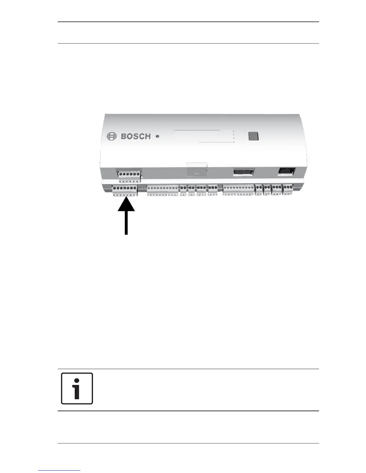
Connect the power supply to the POWER 7-pin pluggable screw
connector. Refer to Connecting Diagrams, page 63 for a
complete diagram of the power supply connector.
Figure4.6: Location of the power supply connector
Connect an external power supply (10 - 14 Vdc) for the AMC2
device at pin 1 (positive) and pin 3 (0 V) of the pluggable screw
connector.
If an uninterruptible power supply (UPS) is used, the relay
output for power good signals from the UPS is connected to the
following pins:
– pin 4 and 7 for power good AC
– pin 5 and 7 for power good Battery
– pin 6 and 7 for power good DC
Otherwise these pins must be short-circuited.
Notice!
To build a UL listed configuration, refer to UL Requirements,
page 45

 Loading...