Subject to change without prior notice Revised 05-12
6 720 220 045
14
CP/BP Series
concern regarding the quality of the well water
available or should any known hazards exist in your
area, we recommend proper testing to assure the
well water quality is suitable for use with water
source equipment. In conditions anticipating
moderate scale formation or in brackish water, a
cupro-nickel heat exchanger is recommended. In
well water applications water pressure must always
be maintained in the heat exchanger. This can be
accomplished with either control valve or a bladder
type expansion tank.
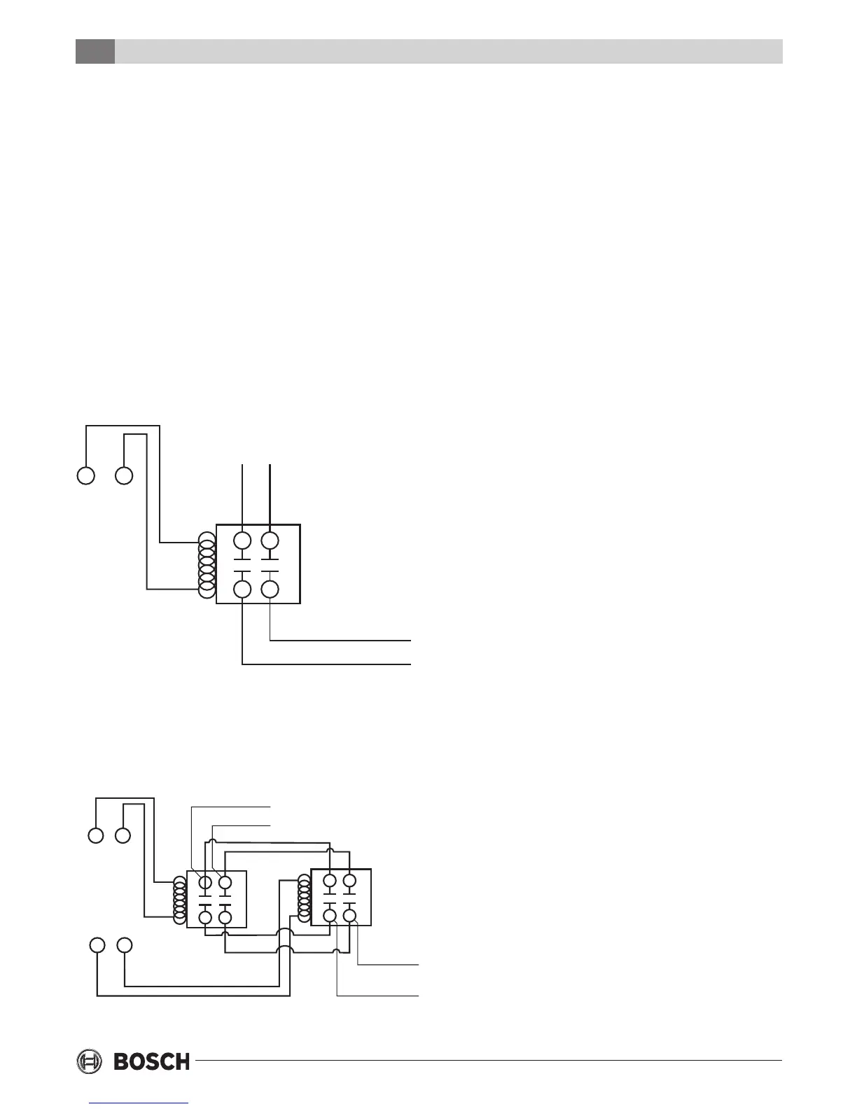
When well water is used exclusively for supplying water
to the heat pump, the pump should operate only when
the heat pump operates. A 24 volt double pole-single
throw (DP/ST) contactor (Figure #6) can be used to
operate the well pump with the heat pump.
POWER SUPPLY
C Y1
UNIT
TERMINAL
STRIP
(24VAC)
POWER TO PUMP
DP/ST RELAY
Y1
Figure #6
When two or more units are supplied from one well,
the pump can be wired (Figure #7) to operate
independently from either unit. An upsized VA
transformer may be required in either case.
Y1
Y1
POWER
TO PUMP
C
2 DP/ST
RELAYS
POWER SUPPLY
UNIT
TERMINAL
STRIP
(24VAC)
C
Figure #7
Pressure/temperature ports are recommended in
both the supply and return lines for system ow
balancing. The water ow can be accurately set by
measuring the water-to-refrigerant heat exchangers
water side pressure drop. See the unit specication
sheets for the water ow and pressure drop
information in the back of this manual.
The discharge water from the heat pump is not
contaminated in any manner and can be disposed
of in various ways depending on local codes (i.e.
discharge well, dry well, storm sewer, drain eld,
stream, pond, etc.)
When using a single water well to supply both
domestic water and the heat pump care must be taken
to insure that the well can provide sufcient ow for
both. In well water applications a slow closing
solenoid valve must be used to prevent water hammer.
Solenoid valves should be connected across Y and
C on the interface board for all. Make sure that the
VA draw of the valve does not exceed the contact
rating of the thermostat.
FRESH WATER SYSTEMS
The Units shall be designed to operate throughout the
range of entering uid temperature of 50°F to 110°F in
the cooling mode and 50°F to 80°F in the heating
mode. Units shall have an operating range of 25 °F to
80°F in the heating mode when equipped with the
optional extended range. In the cooling mode, heat is
rejected from the Bosch unit into the water loop. A
cooling tower provides evaporative cooling to the loop
water thus maintaining a constant supply temperature
to the unit. When utilizing open cooling towers,
chemical water treatment is mandatory to ensure the
water is free from corrosive elements.
A secondary heat exchanger (plate frame) between
the unit and the open cooling tower may also be
used. It is imperative that all air be eliminated from
the closed loop side of the heat exchanger to insure
against fouling.
In the heating mode, heat is absorbed from the
water loop. A boiler can be utilized to maintain the
loop at the desired temperature.
Fresh Water Systems
 Loading...