6 720 220 045
Revised 05-12 Subject to change without prior notice
7
CP/BP Series
capacity to handle the air required for the unit
application. If the duct system is too small, larger
ductwork should be installed. Check for existing
leaks and repair as necessary to ensure a tight air
seal within duct. The duct system and all diffusers
should be sized to handle the designed air ow
quietly. To maximize sound attenuation of the unit
blower, the supply and return air plenums should
be insulated. There should be no direct straight air
path thru the return air grille into the heat pump.
The return air inlet to the heat pump must have at
least one 90 degree turn away from the space
return air grille. If air noise or excessive air ow are
a problem, the blower speed can be changed to a
lower speed to reduce air ow. (Refer to ECM
motor speeds and settings in Table #1)
Always disconnect power to the unit before
changing motor speed to prevent damage to
the motor, injury or death due to electrical
shock.
ELECTRICAL
Always disconnect power to the unit before
servicing to prevent injury or death due to
electrical shock or contact with moving parts.
All eld wiring must comply with local and national
re, safety and electrical codes. Power to the unit
must be within the operating voltage range
indicated on the unit’s nameplate. On three phase
units, phases must be balanced within 2%.
Operating the unit with improper line voltage
or with excessive phase imbalance is
hazardous to the unit and constitutes abuse
and is not covered under warranty.
Properly sized fuses or HACR circuit breakers must
be installed for branch circuit protection. See
equipment rating plates for proper size.
The heat pump units are provided with a concentric
knock-out in the front right corner post for
attaching common trade sizes of conduit. Route
power supply wiring through this opening. Flexible
wiring and conduit should be used to isolate
vibration and noise from the building structure. Be
certain to connect the ground lead to the ground
lug in the control box. Connect the power leads as
indicated on the unit wiring diagrams.
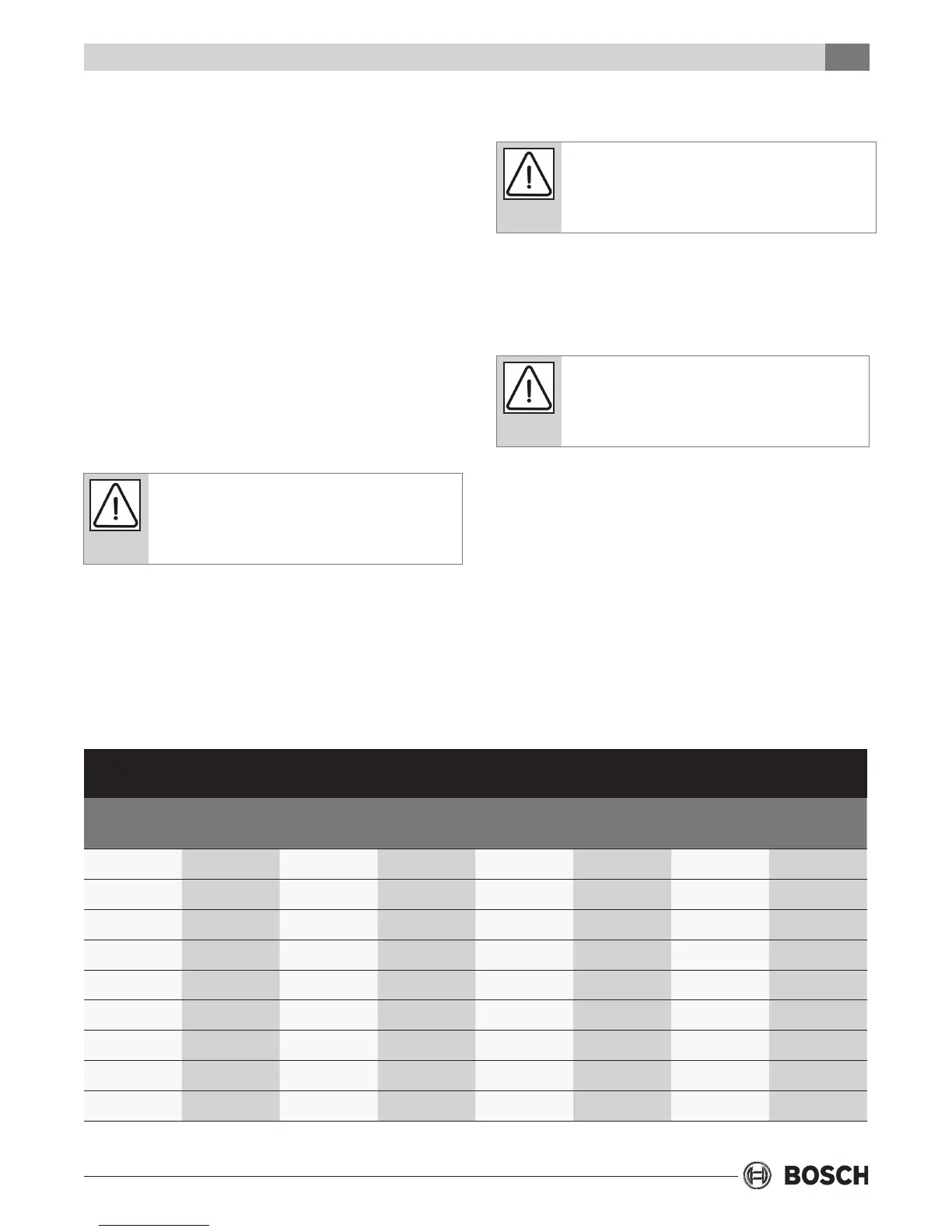
Table 1: CP/BP Motor CFM Selection (ECM Motor)otor Only)
Units
Motor Part
Number
Motor HP Tap1 Tap2 Tap3 Tap4 Tap5
CP/BP015 450-153 1/3 LOW MED HIGH - -
CP/BP018 450-153 1/3 - LOW - MED HIGH
CP/BP024 450-157 1/3 LOW MED HIGH - -
CP/BP030 450-154 1/3 LOW MED HIGH - -
CP/BP036 450-158 3/4 LOW MED HIGH - -
CP/BP042 450-155 3/4 LOW MED HIGH - -
CP/BP048 450-155 3/4 - LOW MED HIGH -
CP/BP060 450-156 1 LOW MED HIGH - -
CP/BP070 450-156 1 LOW - - MED HIGH
Electrical
 Loading...