18
Installation (only for approved contractors)
Therm 4000 S – 6 720 815 298 (2017/05)
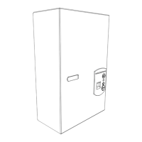
Fig. 12 Minimum clearances
[A] At the side 1cm
[B] 40 cm
[C] At the front 2cm
Minimum clearances for the flues
Fig. 13 Minimum clearances for the flues
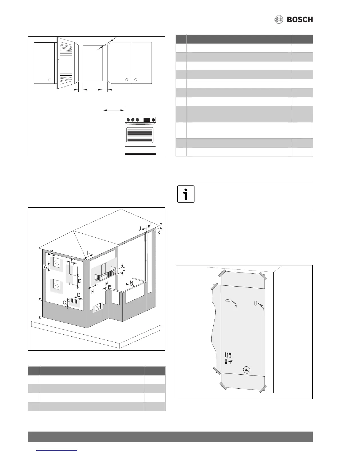
5.4 Fitting the wall mounting bracket
No special wall protection is required. The wall must be even
and with sufficient load-bearing capacity to hold the weight of
the device.
▶ Remove the device from the packaging.
▶ Fasten the packaging to the wall to mark the position of the
holes.
Fig. 14 Mounting template
▶ Remove the mounting template from the wall.
Minimum clearances for the flues (mm)
A Below a window 600
B Beside a window 400
C Below an air inlet or outlet opening 600
D Beside an air inlet or outlet opening 600
Table 15
E Vertical clearance between two flues 1 500
F Horizontal clearance between two flues 600
G Below a balcony 300
H Beside a balcony 1 000
I To the floor or another floor of the building 2 200
J To vertically or horizontally running flues 300
K Below the roof edge 300
L To the wall / internal corner / external corner in
the case of buildings without windows
300
M To the wall / internal corner / external corner in
the case of buildings with windows
1 000
N To the front wall with windows 3 000
N To the front wall without windows 2 000
Prior to fitting the wall mounting bracket,
check whether the connections for water,
gas and flue accessories are available.
Minimum clearances for the flues (mm)
Table 15
 Loading...