24
Gas regulating (only for approved contractors)
Therm 4000 S – 6 720 815 298 (2017/05)
▶Press the key.
The display shows "P1".
The setting of the maximum gas volume is completed.
7.4.3 Setting the minimum gas volume (parameter P2)
▶ Press until the display shows "P2".
▶Press the key.
The display shows "E".
▶ Press until the display shows "L2".
▶Press the key.
▶ Open one hot water tap.
The minimum gas volume can be set at the device.
▶ Press or , until the pressure gauge displays the
value given in Tab. 17.
▶Hold down for 3 seconds.
The value flashes as confirmation.
▶Press the key.
The display shows "L2".
▶ Close the hot water tap.
▶ Press until the display shows "E".
▶Press the key.
The display shows "P2".
▶ Press the , and keys simultaneously and
hold them down for 3 seconds.
The display shows the selected temperature.
▶ Disconnect the pressure gauge from the test ports [A] and
[B].
▶ Tighten the sealing screws for test ports [A] and [B].
The setting of the minimum gas volume is completed.
7.4.4 Adjustment of the burner nozzle pressure
(parameter P0)
▶Call up Service mode ( Section 7.2).
The display shows "P2".
▶ Press until the display shows "P0".
▶ Press the key.
▶ Open one hot water tap.
Wait until the measured value on the pressure gauge has
stabilised.
▶ Press or , until the pressure gauge displays the
value given in Tab. 17.
▶ Hold down for 3 seconds.
The value flashes as confirmation.
▶ Press to leave the mode.
The display shows P0.
▶ Close the hot water tap.
▶ Remove the pressure gauge from the test port.
▶ Tighten the sealing screw on the test port [B].
The adjustment of the burner nozzle pressure is
completed.
7.4.5 Factory setting (parameter P4)
▶Call up Service mode ( Section 7.2).
The display shows "P2".
▶ Press until the display shows "P4".
▶ Press the key.
The display shows "E".
▶ Press the key, until the display shows "rP".
▶ Press the key.
The display shows "P1".
If the value cannot be reached:
▶ Adjust the burner pressure (Section
7.4.4) and repeat the setting
procedure.
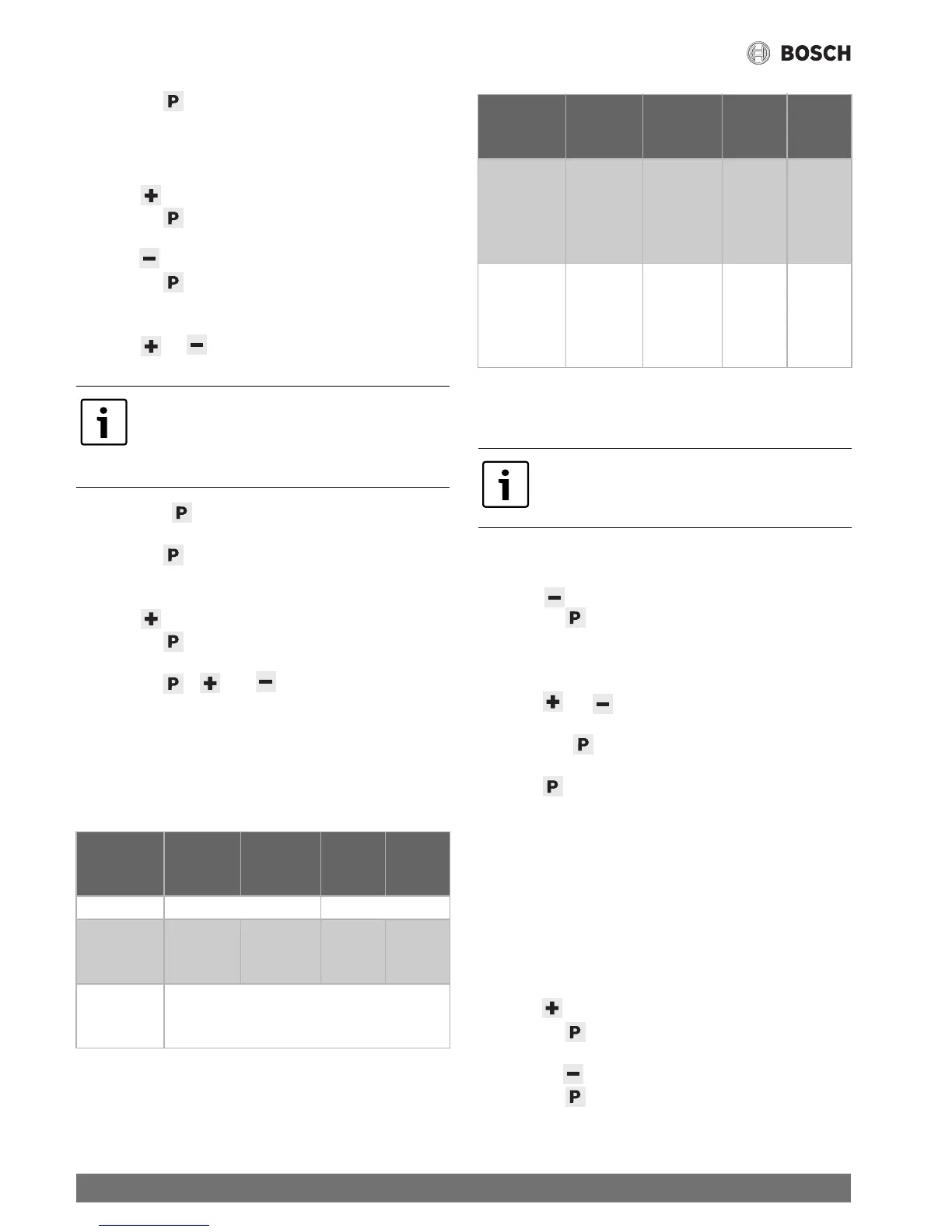
Natural
gas H
(G20)
Natural
gas L
(G25)
Butane Propane
Ø injector 1.8 1.3
Gas supply
pressure
(mbar)
20 25 28-30 /
50
30 / 37/
50
Nozzle
pressure
(mbar) - P0
1.2
Table 17 Burner pressure
Adjustment
range of
max. nozzle
pressure
(mbar) - P1
4,1 - 4,5 6,3 - 6,7 4,9 - 5,3 6,2 - 6,6
Adjustment
range of
min. nozzle
pressure
(mbar) - P2
0,5 - 0,7 0,8 - 1,0 0,6 - 0,8 0,8 - 1,0
It is only necessary to adjust the burner
pressure, if the values "L1" and "L2" cannot
be reached:
Natural
gas H
(G20)
Natural
gas L
(G25)
Butane Propane
Table 17 Burner pressure
 Loading...