Do you have a question about the Bosch HPC and is the answer not in the manual?
| Brand | Bosch |
|---|---|
| Model | HPC |
| Category | Controller |
| Language | English |
Explains symbols used in warnings and important information for clarity and safety.
Crucial safety precautions and hazard warnings for installation and servicing.
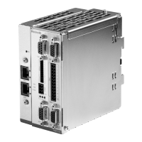
Overview of the Heat Pump Controller (HPC) and its function in interfacing with the thermostat.
Digital interface for configuring, commissioning, and troubleshooting the HPC via a mobile app.
Details on the HPC's digital inputs, analog inputs, outputs, and physical characteristics.
Specifies the rectangular pattern and dimensions for mounting the HPC unit.
Describes the integrated loop pump control relay function for energizing pumps or solenoid valves.
Lists available HPC settings configurable via the Bosch EasyStart app.
Explains the 'Alarm Mode' setting for fault alarms, constant or pulsed operation.
Details on setting up hard lockout conditions based on multiple faults within a timeframe.
Information on configuring fan motor CFM/Ton and understanding fan motor specifications.
Explains operational delays like Random Start-Up Delay and Test Mode functionality.
Describes the unit's operational logic for cooling and heating modes.
Details on fan engagement, speed control, and loop pump energization during heating/cooling.
Explains heating operation, auxiliary heat engagement, and compressor/heater interaction.
Covers Emergency Heating, Heat Recovery Package (HRP), Comfort, and Economy modes.
Explains the HRP system, components, and conditions for potable water heating.
Describes dehumidification settings and Latching/Unlatching modes for staging control.
Monitors Y1 call and protects compressor from High/Low pressure faults via HPS/LPS.
Details Brownout Protection, Low Loop Water Protection, and Water Flow Detection mechanisms.
Monitors condensate drain pan level to prevent overflow and protect the unit.
Explains the function and location of DAT and RAT sensors for air temperature monitoring.
Covers LWT, EWT, and FZC sensors for water loop monitoring and freeze prevention.
Details FZE sensor for evaporator freeze protection and DRT sensor for HRP monitoring.
Describes the DWT sensor's role in monitoring tank temperature for Heat Recovery Package operation.
Validates thermostat signals and provides I/O details for diagnostics.
Identifies fuses for thermostat wiring and the CR2032 board battery.
Explains blink codes and LED status for fault identification.
Describes the behavior and meaning of Heartbeat LED and Status LED for operational feedback.
Details LED indicators for power status, high pressure, and low pressure faults.
Explains the Heartbeat LED function and provides a thermistor resistance vs. temperature curve.
Provides contact info, recommended tools, and how to find unit model/serial numbers.
Step-by-step guide for physically replacing the HPC board and reconnecting components.
Guide for using the Bosch EasyStart app to update firmware and set unit configurations.
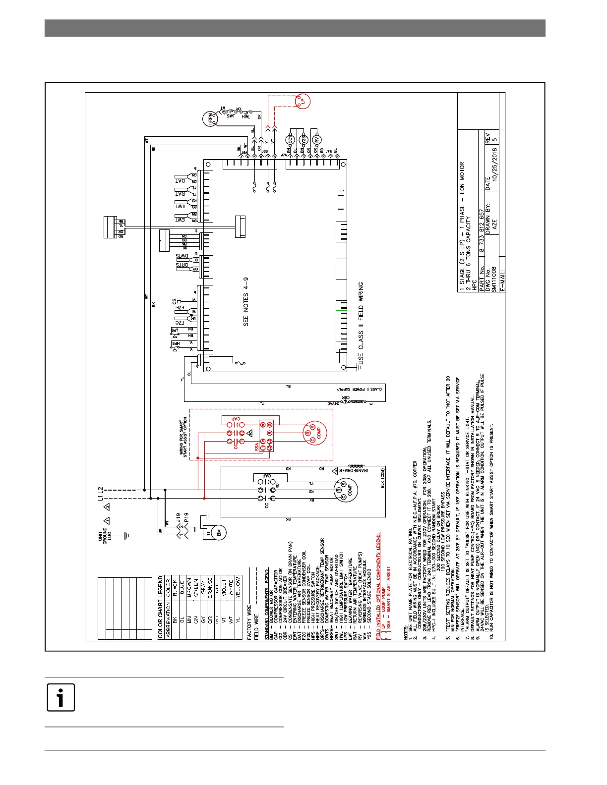
Illustrates wiring for a single-stage, 2-step unit with an EON motor.
Shows wiring for a single-stage, 2-step unit with EON motor and electric heat.
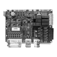
Illustrates the component layout within the unit's electrical box.
Details the standard coded connectors for thermostat wiring to the HPC.
Shows wiring diagrams for common, dry contact, and 24VAC thermostat alarm supports.
Provides a glossary of acronyms and technical terms used throughout the manual.
Guidelines for safe decommissioning, component recycling, and hazardous waste disposal.
Forms for recording customer details, unit specifications, and operating conditions.
Table comparing default and new values for EasyStart configurable settings.
Blank page for user notes.