Thermostat Connections | 33Heat Pump Controller
8733819577 (2019/02)Heat Pump Controller Subject to change without prior notice
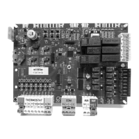
THERMOSTAT CONNECTIONS
The HPC is equipped with a standard coded
Thermostat interface connectors. Refer to the
figures below.
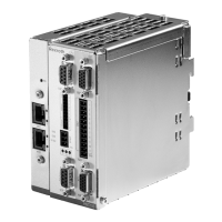
Fig. 39 HPC Thermostat Connectors
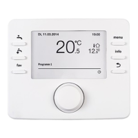
Fig. 40 Generic Thermostat Connections
The HPC also provides visual indication (green
LED) when the Thermostat has a call for a signal.
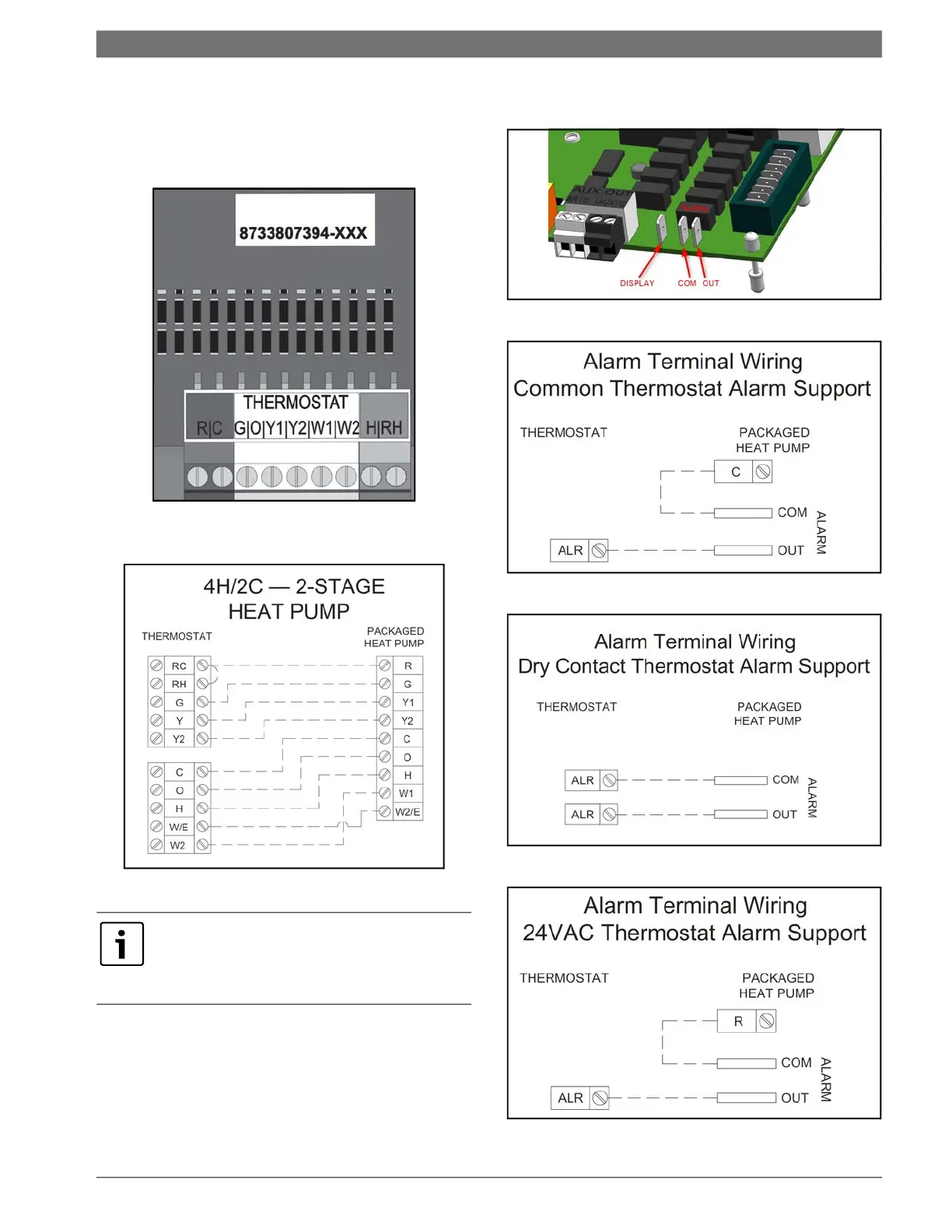
ALARM TERMINAL WIRING
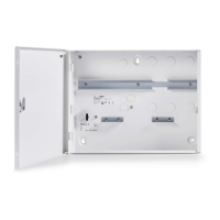
Fig. 41 Alarm Terminal Connectors on the HPC Board
Fig. 42 Generic Thermostat Connections
Fig. 43 Alarm Support for Dry Contact Thermostats
Fig. 44 Alarm Support for 24VAC Thermostats
When using a 2-cool, 3-heat thermostat both the
W1 & W2 on the Heat Pump and W2 & EM on
the thermostat must be connected together via
a jumper.
 Loading...