4. M a in t e n a n c e
4.1 Cleaning
The housing of the KTS modules are only to be cleaned
using a soft cloth and a neutral cleaning agent. Do not
use any abrasive cleaning agent or rough cleaning cloths.
4.2 Maintenance
The tab Cu stom er serv ice can be used for performing
various tests in DDC. A portion of these tests can only
be performed by customer service.
4.3 S pare and w earing parts
R eplacement and wear parts only concern parts
received in the respective delivery.
Des cription Ord er Num b er
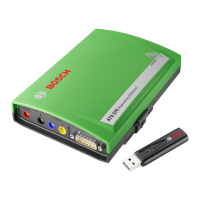
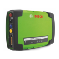
System tester KTS 5 3 0 1 6 8 7 0 2 2 4 3 7
System tester KTS 5 4 0 1 6 8 7 0 2 2 4 3 6
System tester KTS 5 7 0 1 6 8 7 0 2 2 9 9 4
Adapter insert 1 6 8 8 0 0 0 3 4 9
OBD diagnosis cable 3 m (KTS 5 3 0 )
(<)
1 6 8 4 4 6 5 5 5 7
OBD diagnosis cable 1 .5 m (KTS 5 4 0 /5 7 0 )
(<)
1 6 8 4 4 6 5 5 5 5
Power pack
Power supply cable
(<)
1 6 8 7 0 2 2 8 8 9
1 6 8 4 4 6 1 1 0 6
M easuring cable blue (KTS 5 3 0 /5 4 0 )
(<)
1 6 8 4 4 3 0 0 6 6
M easuring cable yellow (KTS 5 3 0 /5 4 0 )
(<)
1 6 8 4 4 3 0 0 6 7
G round cable black
(<)
1 6 8 4 4 3 0 0 6 8
M easuring cable red/black (KTS 5 7 0 )
(<)
1 6 8 4 4 6 3 2 1 4
M easuring cable blue/yellow (KTS 5 7 0 )
(<)
1 6 8 4 4 6 3 5 5 0
Test tip red (1 x , with KTS 5 7 0 2 x ) 1 6 8 4 4 8 5 0 3 5
Terminal clip black
(<)
1 6 8 4 4 8 0 0 2 2
Connection cable USB 3 m
(<)
1 6 8 4 4 6 5 5 6 2
UN I connection cable 4 core
(<)
1 6 8 4 4 6 3 5 3 9
Case 1 6 8 5 4 3 8 1 4 5
M ount parts set 1 6 8 7 0 0 1 8 5 3
Bluetooth USB adapter (KTS 5 4 0 /5 7 0 ) 1 6 8 7 0 2 3 3 8 2
(<)
P a r t s u b je c t to w e a r
0
5 . T e c h n ic a l d a t a
5 .1 G eneral d ata
Property V alue/ R ange
Operating voltage 7 V DC — 3 0 V DC
Power consumption through
vehicle battery or power supply
approx . 6 W att
Dimensions (L x W x H) 1 7 0 x 1 2 0 x 4 0 mm
W eight (without connecting cables) 3 2 5 g
Operating temperature 0 ° C – 4 0 ° C
R elative humidity 9 0 % (at 2 5 ° C)
5 .2 Interface protocols
The following interfaces with respective protocols are
supported for controller diagnosis in conformance with
ISO 1 5 0 3 1 :
ISO 9 1 4 1 -2 (Communications lines K and L)
SAE J 1 8 5 0 V PW and SAE J 1 8 5 0 PW M
(Communication lines BUS+ and BUS-)
CAN ISO 1 1 8 9 8 ISO 1 5 7 6 5 -4 (OBD)
(Communication lines CAN -H and CAN -L)
CAN Single W ire
CAN Low Speed
5 .3 Pow er pack
Property V alue/ R ange
Input voltage 9 0 — 2 6 4 V AC
Input frequency 4 7 — 6 3 Hz
Output voltage 1 5 V
Operating temperature 0 ° C — 4 0 ° C
5 .4 Multim eter s pecifications
CH1 zero potential (blue input is not allowed to be
connected with voltage carrying measuring points).
Input resistance > 9 0 0 k Ohm.
CH2 potential based (black ground input
must be connected with vehicle ground).
Input resistance > 9 0 0 k Ohm.
5 .4.1 DC m eas urem ent (CH1 and CH2)
Property V alue/ R ange
M easurement range 2 0 0 mV — 2 0 0 V
Precision CH1
± 0 .7 5 % of measurement value,
additional ± 0 .2 5 % of measurement range
Precision CH2
± 2 % of measurement value,
additional ± 0 .5 % of measurement range
R esolution
1 0 0 µ V — 1 0 0 mV
(depending on measuring range)
R
R
R
R
R
R
R
 Loading...