CONNECT THE ROUTER AND THE
ROUTER TABLE SWITCH
To prepare for use of the switch:
1. Make sure the router table’s switch and the
router table switch are both turned off.
2. Plug the router table switch cord to wall
outlet.
3. Plug the router into the "pigtail" socket on
the router table switch.
4. Lock router switch on: squeeze trigger,
depress lock-on button, and release trigger.
5. Use the router table switch to start and stop
the router.
DEPTH ADJUSTMENT
(See pages 11 & 12)
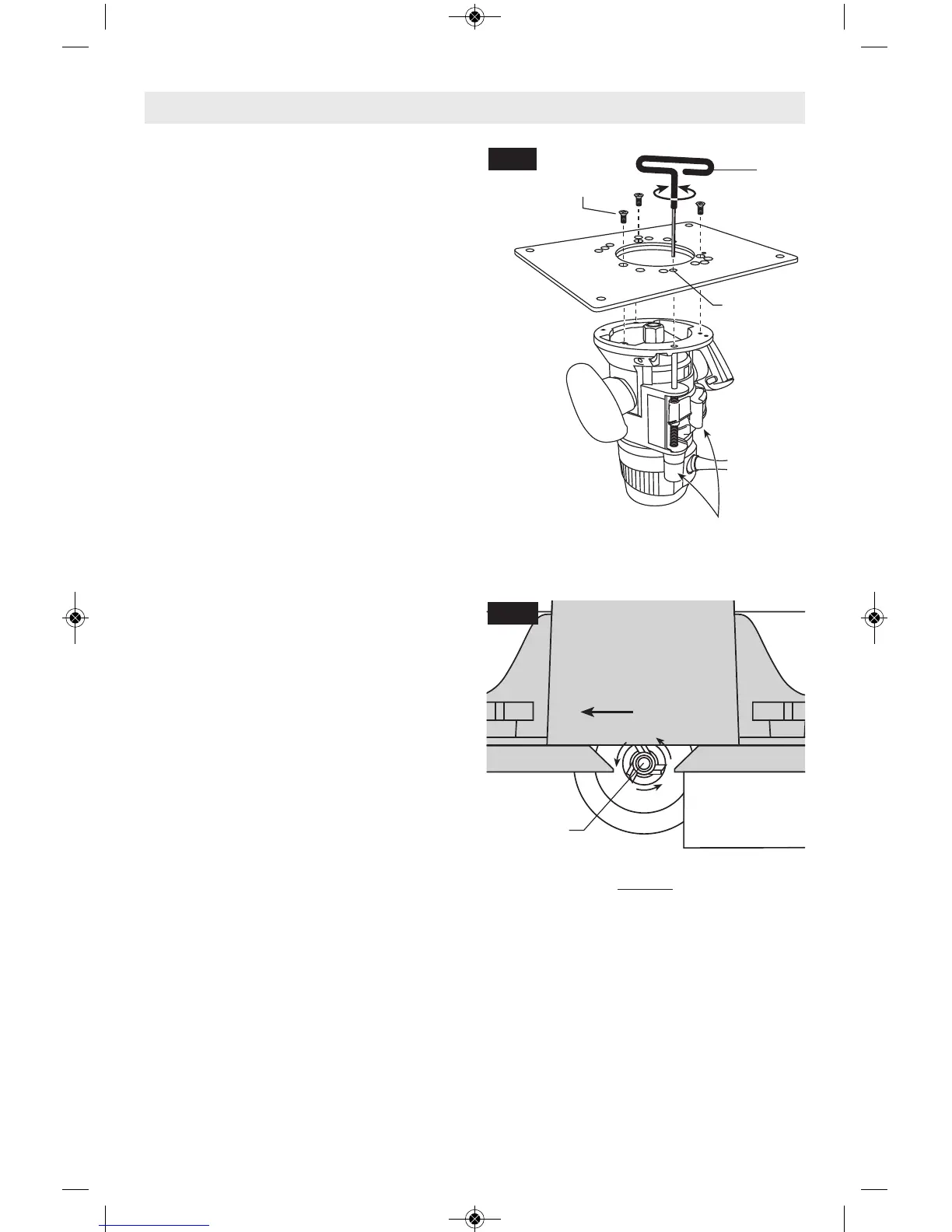
FEEDING THE WORKPIECE
ON A ROUTER TABLE
Always use your router table's fence or starter
pin and the appropriate guard and follow the
router table's instruction manual. ALWAYS
feed the workpiece from right to left across the
front of the bit. On Bosch router tables, the
correct feed direction is also shown on fence
housing and on the featherboards, when they
have been properly installed. (Fig. 22)
Whenever possible, when using the fence,
use a push stick to push the workpiece,
especially when working with narrow pieces.
For complete instructions on operation of a
router in a router table, please refer to the
instructions that come with the router table.
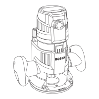
Shown after
subbase has
been removed
Hole for Hex
Wrench
Quick-release clamp lever and
depth adjustment controls should
face the front of the router table
Mounting
Plate
M4
Screw
Hex
Wrench
-23-
Workpiece
DIRECTION
OF FEED
Bit Bearing
TOP VIEW
NOTE: For clarity, guard and featherboard
removed from drawing.
Fence Face Fence Face
FIG. 21
FIG. 22
Use in Router Table
 Loading...