12
5.4 Output Connections
In a full-range system that includes only 402
TM
or 802
®
loudspeakers, use the controller’s HIGH FREQ OUTPUT
jacks to drive the amplifier(s) feeding the loudspeakers.
Do not use the LOW FREQ OUTPUT jacks. The MODE
switch should be set to Mode 1 (FR).
In a bi-amplified system, use the controller’s HIGH
FREQ OUTPUT jacks to drive the amplifier(s)
feeding the high frequency loudspeakers (402
or 802 loudspeakers). Connect the LOW FREQ
OUTPUT jacks to the amplifier(s) driving the bass.
If the system has mono bass, use only the Channel
1 (left hand) LF output jack, and make sure that the
OUTPUT MODE switch is set to SUM.
For best audio performance, install all mixing or signal
processing equipment before the controller in the
audio chain. The 402C or 802C II systems controller
should be the last device in the audio chain before
the amplifier(s).
Here is how to wire the HIGH FREQ OUTPUT and
LOW FREQ OUTPUT jacks on the controller. When
the OUTPUT MODE switch is set to SUM, use only
the CH1/SUM (left-hand) LOW FREQ OUTPUT jack.
NOTE: The pin numbers for each controller output
are shown in small type inside the jacks.
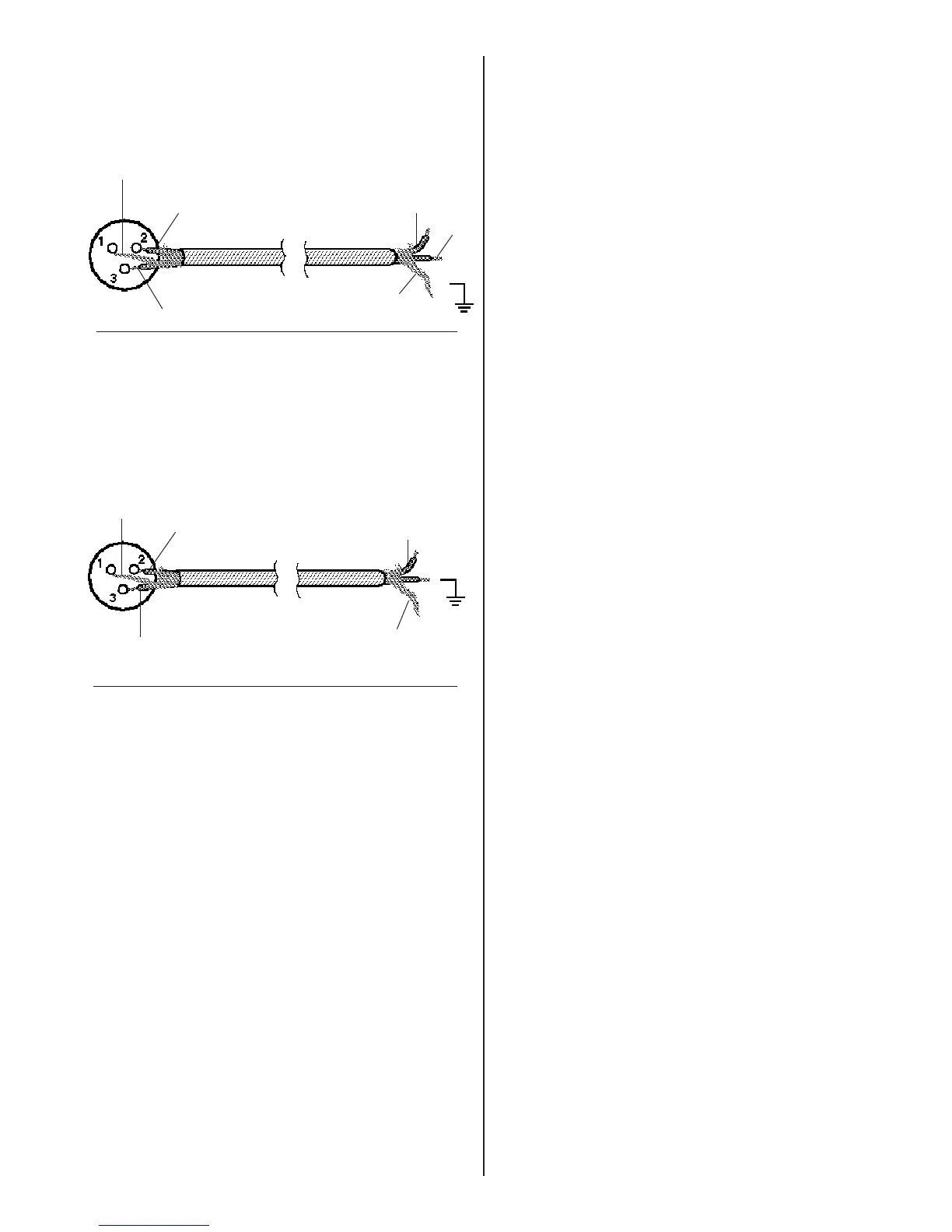
If the amplifier has balanced inputs (see Figure 14):
1. Connect the controller’s PIN 2 (+) output
terminals to the amplifier’s hot, tip, or high
terminals. (These are usually pin 2 on XLR-
equipped amplifiers).
2. Connect the controller’s PIN 3 (-) output
terminals to the amplifier’s low, ring, or minus
terminals. (These are usually pin 3.)
3. Connect the controller’s PIN 1 GND output
terminals to the cable shield and to PIN 1 (XLR)
or ground at the amplifier.
If the amplifier has unbalanced inputs (Figure 15):
1. Connect the controller’s PIN 2 (+) output
terminals to the amplifier’s hot, tip, or high
terminals.
2. Connect the controller’s PIN 3 (-) output
terminals to the amplifier’s shield or ground
terminals. Use one of the two cable conductors.
3. Connect the controller’s PIN 1 GND output
terminals to its cable shield. Do not connect at
the amplifier end.
Figure 15
Connections from the systems controller to an
amplifier with unbalanced inputs.
Shield (no
connections)
– (GND)
+
Shield
+
–
Amplifier
input
From
controller
–
Shield (no
connections)
–
+
+
Figure 14
Connections from the systems controller to an
amplifier with balanced inputs.
Shield
– (GND)
Amplifier
input
From
controller
 Loading...