13
5.5 Mechanical Connections
The 402
TM
C and 802
®
C II systems controllers are 1
3
⁄
4
”
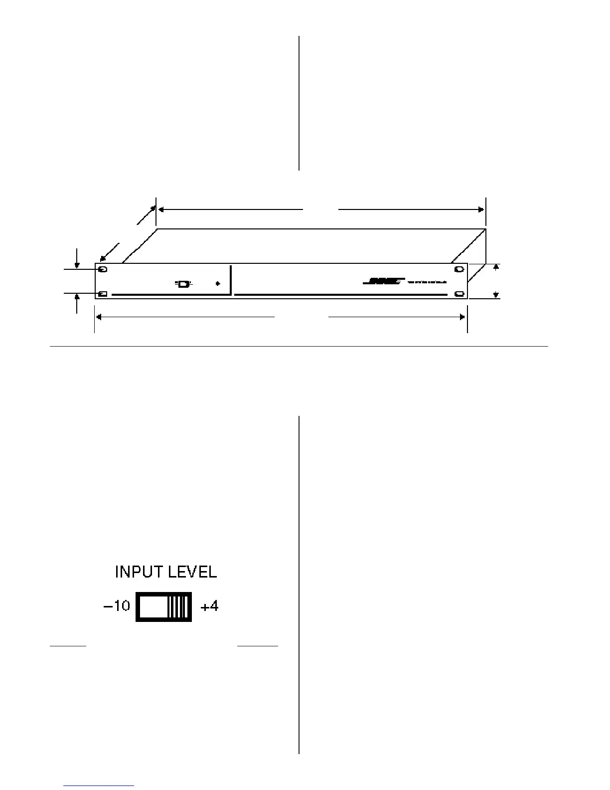
high (1U). They fit a standard 19” rack. Use screws
or bolts that fit the rack you are using. Note the
maximum depth of the rack as shown in Figure 16.
Figure 16
Make sure the rack will hold the controller.
5.6 Basic Operation
These controls are on the rear panel of the 402C or
802C II systems controllers.
INPUT LEVEL
These switches for each input channel adjust the
sensitivity between -10 dB and +4 dB (Figure 17).
To find the nominal output level of the output device
(mixer, signal processor), consult its owner’s guide
or call the manufacturer. Set the controller INPUT
LEVEL switch to the closest number possible.
Do not to overload the inputs of the controller. Set
the INPUT LEVEL switch, and adjust the output
device’s control(s). Keep the signal below the
controller’s maximum input level (+4 dBm or 1.23V
RMS).
Figure 17
The INPUT LEVEL sensitivity switches.
17.4”
44.2 cm
8”
20.3 cm
1.25”
3.18 cm
19”
48.3 cm
1.72”
4.37cm
 Loading...