14
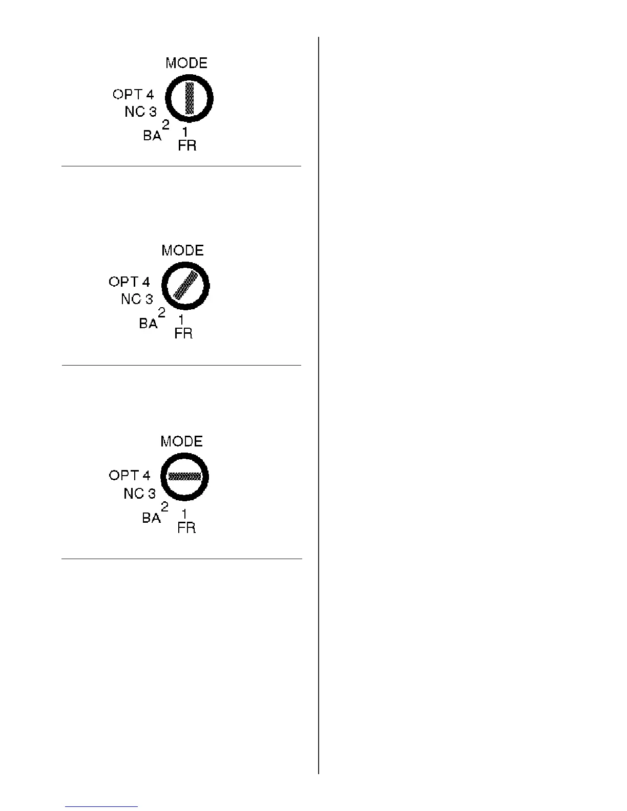
Input MODE
This is a four-position switch. It selects one of three
operating modes for the controller.
Position 1: Full-range (FR) mode. (See Figure 18.)
Use for a full-range system with only 402
TM
or 802
®
loudspeakers. Connect only the controller’s HIGH
FREQ OUTPUT jacks. Do not connect any amplifiers
or loudspeakers to the
LOW FREQ OUTPUT
jacks.
Position 2: Bi-amplified (BA) mode. (See Figure
19.) Use for a 402 or 802 system with 502
TM
B or
502BP Acoustimass
®
bass enclosures. Connect
the controller’s HIGH FREQ OUTPUT jacks to the
amplifier(s) driving the 402 or 802 loudspeakers.
Connect the controller’s LOW FREQ OUTPUT jacks
to the amplifier(s) driving the bass enclosure.
Position 3: No connection (NC). Do not use. It is
not connected in this version of the 402C or 802C II
controller.
Position 4: Option (OPT) mode. (See Figure 20.)
Use when the system includes an Acoustic Wave
®
Cannon
TM
System II loudspeaker. The corresponding
AWCS
OC-1 option card MUST be installed by authorized
Bose personnel in the controller to achieve correct
performance of the system. Connect the controller’s
LOW FREQ OUTPUT jacks to the amplifier(s) driving
the bass.
Figure 18
Input MODE switch in position 1: FR (full-range)
mode.
Figure 20
Input MODE switch in position 4: OPT (option)
mode.
mode.
Figure 19
Input MODE switch in position 2: BA (bi-amp)
 Loading...