9
5.0 General
Operating
Instructions
5.1 Unpacking
Unpack the systems controller carefully. Save all
packing materials in case you ever want to ship the
controller back to Bose or an authorized Service
Center. If any part looks damaged, do not use the
controller. Repack it in its carton and notify Bose
®
Service or your authorized Bose Professional
Products dealer immediately.
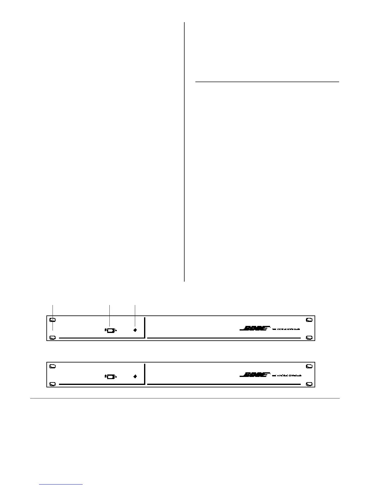
5.2 Controller Parts
Figures 9 and 10 identify main parts of the 402
TM
C
and 802
®
C II systems controllers.
A. Front panel: 1U (1 3/4”) standard height with
two mounting holes on each end.
B. Power switch: O/I (OFF/ON) mains switch.
When it turns on, the signal mutes for one
second before flowing from controller to
amplifier. When it turns off, a relay circuit
immediately mutes the signal for on/off pop
protection.
C. Pilot LED: Lights to show power switch is on and
power is supplied.
Figure 9
Front panels of the 402C and 802C II systems controllers.
A B C
 Loading...