INSTALLATION
61
|
ENG
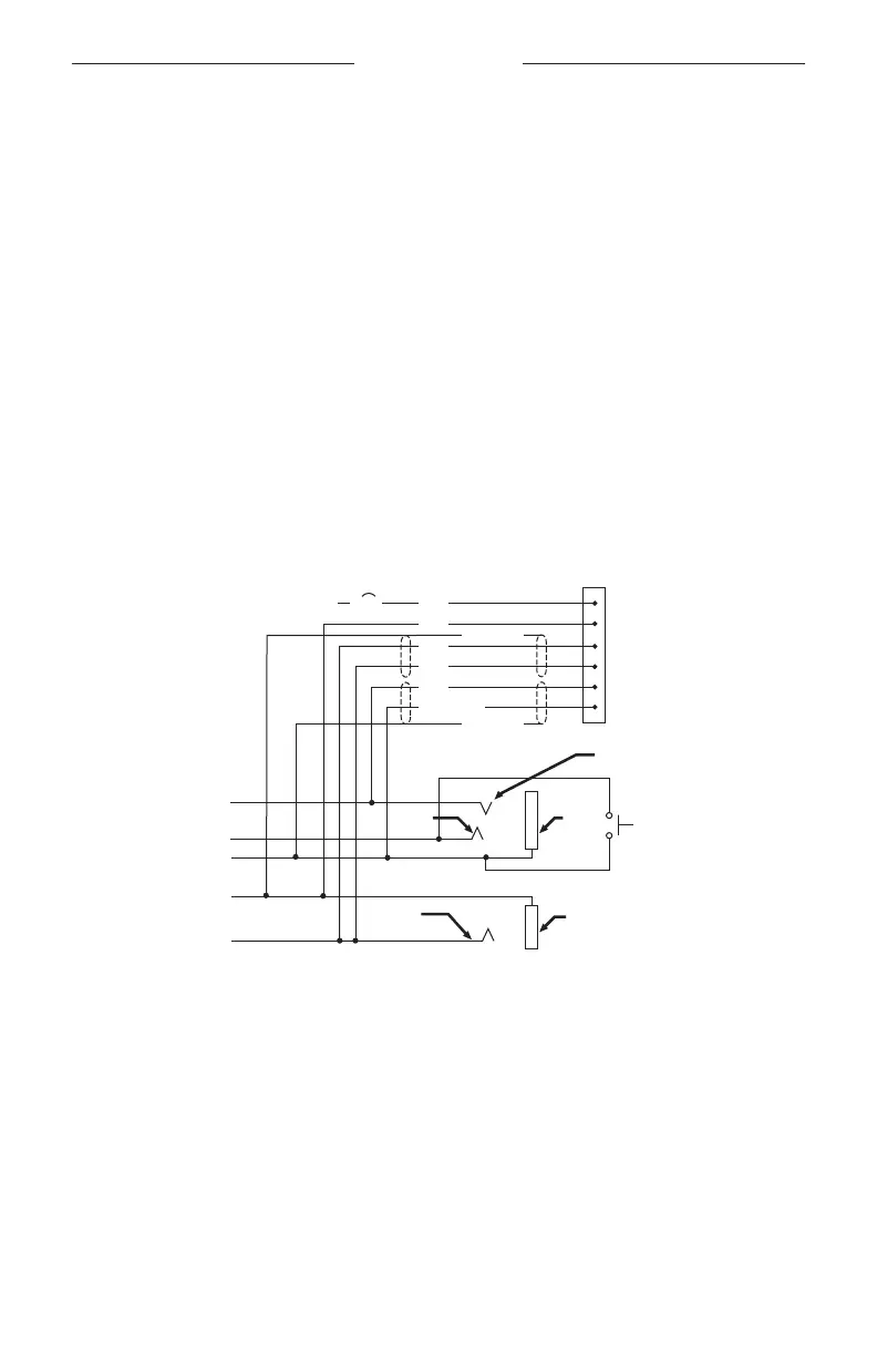
Connect the eight wires as follows:
• Two for the microphone
• Two for audio
• One for power
• One for ground
• Two for audio shields
Audio and microphone wires should be connected to the back of the existing
microphone and headphone jacks, leaving existing jacks intact for use with
conventional headsets. This is usually the fastest installation method.
CAUTION: Do NOT use excessive force or bend the installed connector. This may
damage or break internal solder joints.
NOTE: The aircraft panel connector cannot be installed in an audio system using
transformer-coupled audio outputs. Contact Bose customer service.
Mono connection diagram
10-32
V DC
1/2A
1 V+IN
2 GND
3 COMM L
4 COMM R
5 MIC HI
6 MIC LO
RED
WHT
BLU
WHT
WHT/BLU
BLK/WH
BLK/WH
BLK
Ring
(audio)
Existing PTT
switch
and wiring
(no connection to
Bose headset)
Microphone - Jack
Tip
(PTT)
Barrel
(gnd)
Headphone - Jack
Barrel
(audio gnd)
Tip
(phone audio)
Existing wiring to
aircraft intercom/
audio panel
 Loading...