Page 14 User Guide English
Installation and Operating Guide pro.Bose.com
Front Panel
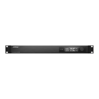
Figure 3. Front Panel View
1. LED Indicators: Power, Signal, Ethernet and Serial indication. (See “Front Panel LED Indicators” below.)
2. Ethernet Connector: RJ-45 jack for front panel network connectivity. (See “Network Connections” on page 19.)
Rear Panel
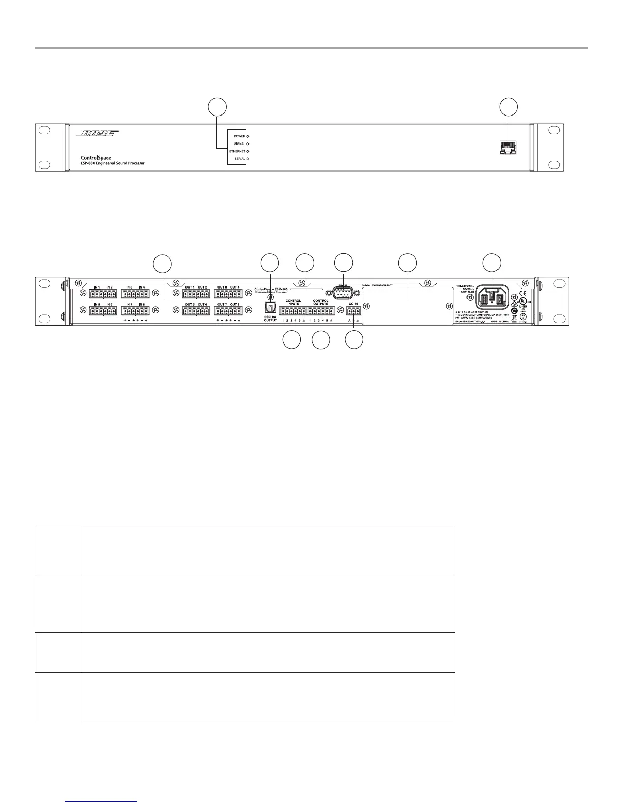
Figure 4. Rear Panel View
1. Analog audio connectors: Mic/line-level balanced input and line-level output connectors.
(See “Analog Audio Connections” on page 16.)
2. ESPLink output connector: For use with ESPLink-equipped PowerMatch
®
amplifiers.
3. Chassis serial number.
4. RS-232: 5-wire, RS-232 (DTE) serial interface connection. (See “RS-232 Connector” on page 17.)
5. Digital expansion slot: Supports optional digital expansion cards.
6. AC Mains receptacle: Power cord connection. (IEC 60320-C14 inlet).
7. CC-16 connector: RS-485 network connection for up to 15 Bose CC-16 zone controllers. (See “CC-16 Connector” on page 17.)
8. Control Outputs connector: Five general-purpose control outputs. (See “General Purpose Outputs” on page 18.)
9. Control Inputs connector: Five general-purpose inputs. (See “General Purpose Inputs” on page 18.)
Front Panel LED Indicators
POWER
Power, booting, or fault-state indication
• Green: Power on, normal operation
• Yellow: Booting
• Red: Fault error (See “Troubleshooting” on page 20.)
SIGNAL
Prioritized signal status indication of all audio input and output channels, listed by order of signaling priority.
For precise metering and gain control, connect using ControlSpace
®
Designer
™
software.
• Green: Signal present on one or more channels
• Yellow: Signal level optimal (-20 dBFS to -2 dBFS) on one or more channels
• Red: Clipping (> -2 dBFS) found on one or more channels
ETHERNET
Connection status indication of front panel and/or option card Ethernet ports.
• Green: Link established
• Yellow: Tx/Rx activity
SERIAL
RS-232 and CC-16 serial command status indication.
• Green: CC-16 controller command transmitted
• Yellow: CC-16 controller command received
• Red: RS-232 Rx/Tx activity
1
2
2
4
3
5
6
9
7
8
1
 Loading...