English User Guide Page 19
pro.Bose.com Installation and Operating Guide
8. Network Connections
ESP-880/1240/4120 processors feature two network connection methods:
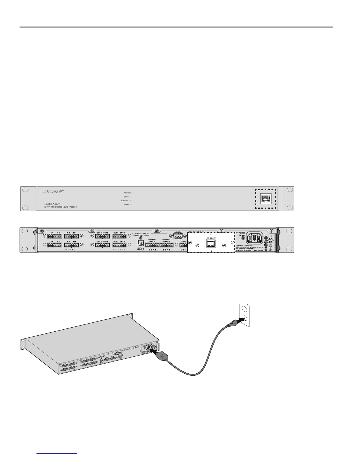
1. A front-panel RJ-45 network port (See figure 9.)
2. Optional rear-panel network cards (See figure 10.)
The front-panel connection is intended for localized configuration and monitoring. When used with a rear-panel network card, the front-
panel RJ-45 connector can serve as a convenient passthrough to the network connection on the rear panel. For added security, the
front panel connector is lockable using ControlSpace
®
Designer
™
software.
Network option cards can serve as the primary means for configuration, control, and monitoring of an ESP through connection to a
larger network.
Note: When using a rear-panel network card, do not plug both the front and rear-panel RJ-45 connections into a common network
switch or router.
Use a F/UTP Cat5e cable (not supplied) to connect a PC to the ESP processor. This connection can be made either directly to the
processor or through a switched Ethernet network. Once powered, the ESP processor will try to retrieve an IP address from an available
server. If unsuccessful, the ESP processor will timeout and revert to a default IP address as below:
Default IP addresses per model:
ESP-880:
192.168.0.161
ESP-1240: 192.168.0.162
ESP-4120: 192.168.0.163
For more information, see the ControlSpace Designer Software Guide from pro.Bose.com or inside the software help system.
Figure 9. Front Panel Network Port Location
Figure 10. Optional Rear Panel Network Card Location
9. Power Cord Connection
ControlSpace
®
ESP-880/1240/4120 processors can operate with AC mains line voltages from 85 to 264 volts AC at 50/60 Hz and uses
a removable IEC power cord. Power consumption is less than 15VA at 122ºF (50ºC) ambient.
To power on the ESP processor, simply plug in the rear-panel IEC power cord. Once powered, boot times may be as long as 40
seconds. A solid green Power LED on the front panel indicates that the processor is ready for connection/operation.
Figure 11. Power cord connection
10. Configuration with ControlSpace Designer Software
With a network connection in place and ControlSpace Designer software installed, use the Update Firmware tool inside ControlSpace
Designer software to scan and update the ESP processor. Once the ESP processor status reads "Up-to-Date" in the firmware panel,
proceed with your system design using ControlSpace Designer software. For full details on using ControlSpace Designer software to
configure, control, and monitor the ESP processor or entire systems built with Bose networked system electronics, visit pro.Bose.com
and download the ControlSpace Software Guide or use the help system inside the software.
 Loading...