14
DISASSEMBLY PROCEDURES
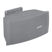
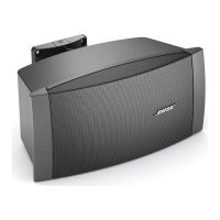
FreeSpace
®
DS 100SE Surface-Mount
Loudspeaker
Note: Refer to Figure 3 for the following
procedures.
1. Grille Removal
1.1 Grasp the grille cap (1) and slide it off
toward the front of the loudspeaker. You will
need to remove both grille caps to be able to
remove the grille (2).
1.2 Using a Phillips-head screwdriver, re-
move the four screws (3) that secure the
grille to the baffle (8). Lift off the grille.
2. Logo Removal
2.1 Perform procedure 1.
2.2 Using a Phillips-head screwdriver, re-
move the screw located on the logo's mount-
ing post. Slide the two washers and spring
(19, 25, 26) off of the logo's post. Lift the logo
(28) off of the grille (2).
3. Tweeter Driver Removal
3.1 Perform procedure 1.
3.2 Using a Phillips-head screwdriver, re-
move the four screws (5) that secure the
2.25" driver (4) to the rotatable array section.
3.3 Lift out the driver. Disconnect the two
Faston connectors.
4. Front Baffle Removal
4.1 Perform procedure 1.
4.2 Using a Phillips-head screwdriver, re-
move the four screws (5) that secure the
tweeter baffle section to the loudspeaker
baffle.
4.3 Lift out the tweeter section and remove
the two main baffle screws (7) that are
located underneath it. Remove the other six
screws that secure the baffle (8) to the
enclosure (10). Lift off the baffle.
5. Woofer Removal
5.1 Perform procedure 1.
5.2 Using a Phillips-head screwdriver, re-
move the four screws (7) that secure the
woofer (6) to the baffle (8).
5.3 Lift out the woofer. Disconnect the two
Faston connectors.
6. Crossover PCB Removal
6.1 Perform procedure 4.
6.2 Remove the four screws (5) that secure
the crossover PCB assembly (9) to the
enclosure.
6.3 Make a note of the wiring configuration
for use during re-assembly. Disconnect the
four Faston connectors that run from the
input cable to the crossover board. Discon-
nect the two Faston connectors that run up
to the woofer. Disconnect the two Faston
connectors that run to the twiddler baffle
section. Lift out the PCB assembly.
7. TAP Rotary Switch Removal
7.1 Perform procedure 4.
7.2 Using a small flat-tip screwdriver, gently
pry underneath the TAP switch knob (21) to
remove it. Take care to not mark the enclo-
sure (10) or baffle (8).
7.3 Using a nut driver, remove the nut that
secures the switch to the baffle. Slide the
switch out of the baffle.
 Loading...