37
DISASSEMBLY PROCEDURE
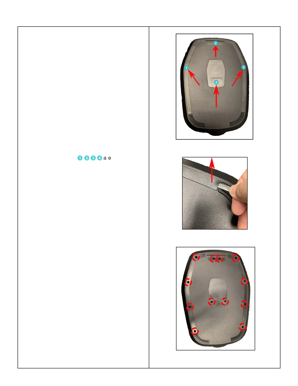
Figure 6. PC Sheets Location
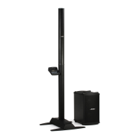
L1 Pro16 Power Stand Procedures
CAUTION: The SMD integrated circuits used
on the Main-I/O Board are extremely sensitive
to ESD damage. Be sure to use an approved
and tested ESD strap that is properly grounded
to your work bench before attempting disas-
sembly or repair of the L1 Pro16 Portable
Line Array System.
1. Enclosure Bottom Removal
1.1 Remove the Mid-high array and Array
extension. Put the Power stand upside down.
Figure 6.
1.2 The PC sheets
1
2
3
4
are secured
with Pressure Sensitive Adhesive - use a
spudger, lift the PC sheets up and grasp and
pull them o. Figure 7.
Re-assembly Note: Be careful to not cause
cosmetic damage to the unit.
Use the new PC sheets to ensure proper
adhesion during reassembly.
1.3 Remove the 12 screws securing the
Enclosure bottom as indicated in Figure 8.
Figure 7. PC Sheets Removal
Figure 8. Enclosure Bottom Screws Removal

 Loading...