37
DISASSEMBLY PROCEDURE
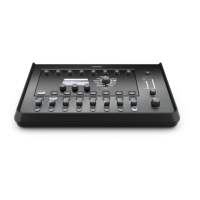
3.2 On the I/O panel, remove the eight plastic
nuts that secure the 1/4” TRS jacks.
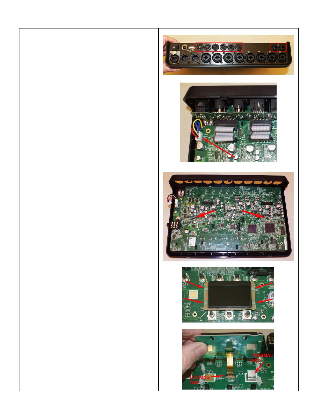
3.3 On the Main PCB, disconnect the wiring
harness for the power switch at connector P2.
3.4 Remove the two screws that secure the Main
PCB to the top housing. Lift out the Main PCB
assembly.
Re-assembly Note: Be sure that the rubber
buttons and phantom power button are properly
aligned with the top housing when re-installing
the Main PCB.
4. LCD Display Assembly Removal
4.1 Perform procedure 3 to remove the Main
PCB assembly.
4.2 Using a pair of needle-nose pliers,
compress the legs of the nylon standoffs that
secure the LCD Display assembly the Main
PCB assembly.
4.3 Carefully lift up the LCD Display assembly.
Lift the black locking tab for the connector and
and unplug the ribbon cable from the Main
PCB at J12.
4.4 Lift off the LCD Display assembly.
Re-assembly note: Be sure that the cube-
shaped thermal pad is in place before re-
installing the LCD display onto the nylon posts.
Refer to the photo at right.
 Loading...