38
TEST PROCEDURE
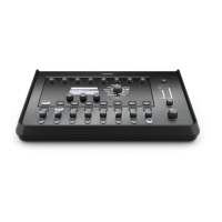
T4S and T8S ToneMatch Audio Engine
Required Equipment:
• T1 power supply, product code 042533
• Audio Signal Generator, Audio Precision ATS-1 Dual Domain or similar (see tests 15 and 16 for note)
• Bose
®
L1 Model II or L1 Model 1S Power Stand with Arrays (optional, see tests 15 and 16)
• dB Meter (Audio Precision ATS-1 has can perform this function also)
• Windows or Mac PC with an open USB slot
• 1 - USB Cable, Type A/B
• Connection cables
Test Mode:
The mixer must be placed into test mode by pressing and holding down the mute buttons 2, 3 and 4 at
the same time when powering on the mixer. This is required for these tests to be accurate. To conrm
that you have entered the test mode using the button method the display should read “Test Mode” and all
of the buttons should be blinking on and off.
The test mode sets the individual channel volumes, the master volume, and the headphone volume
knobs to 50%. All Measurement are to be made using a 20KHz low pass lter.
1/4” TRS Main Outputs L and R Tests - XLR Input 1 - 4 (T4S) or 1 - 8 (T8S)
1. Gain Test
1.1 Rotate the channel 1 Trim control to maximum (fully CW). Apply a balanced 1 kHz, -41dBu sine wave
to the channel 1 XLR input.
1.2 Measure the output level at the 1/4” TRS Main Output L and R jacks. It should be +12.6dBu
+/-0.5dBu.
1.3 Rotate the channel 1 Trim control to minimum (fully CCW). Apply a balanced 1 kHz, -1dBu sine wave
to the channel 1 XLR input.
1.4 Measure the output level at the 1/4” TRS Main Output L and R jacks. It should be +12.2dBu
+/-0.5dBu.
1.5 Repeat steps 1.1 to 1.4 for the remaining inputs.
2. Frequency Response Test
2.1 Rotate the channel 1 Trim control to maximum (fully CW). Apply a balanced 1 kHz, -41dBu sine wave
to the channel 1 XLR input. Reference a dB meter to the output at the 1/4” TRS Main Output L and R
jack.
2.2 Change the input frequency to 20Hz. Measure the output level at the 1/4” TRS Main Output L and R
jacks. Verify that the output level is 0.0dBr +/-0.5dBr.
2.3 Change the input frequency to 20kHz. Measure the output level at the 1/4” TRS Main Output L and R
jacks. Verify that the output level is 0.0dBr +/-0.5dBr.
2.4 Repeat steps 2.1 to 2.3 for the remaining inputs.
 Loading...