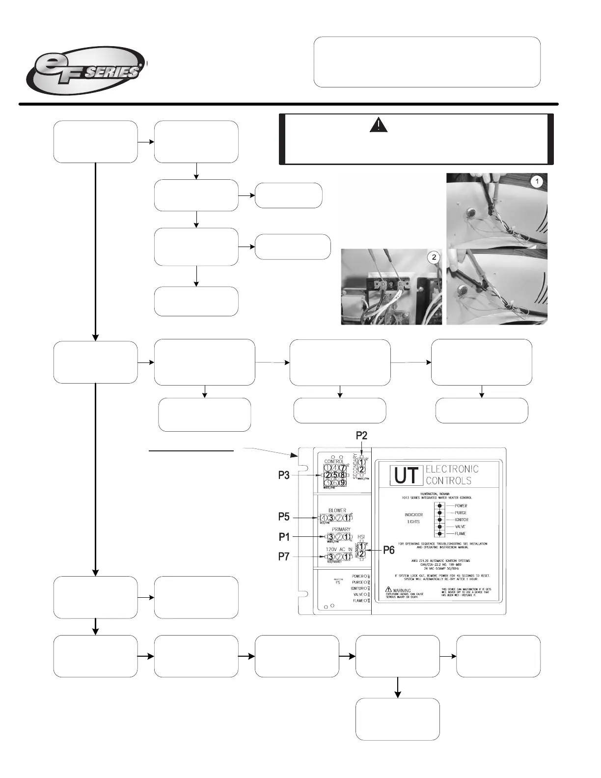
Refer to ignition module
illustration, is there 120VAC
between P1(1) and P1(3)?
Is front panel power
switch light on,
indicating power?
Y
N
Position front panel
power switch to
“ON” position.
Is there 120VAC
across switch?
(see photo 1)
Light burned out,
replace switch.
Y
I
s there 120VAC
a
cross terminal block?
(
see photo 2)
N
D
etermine power
source problem and
correct.
R
epair/replace wire
harness to switch.
Y
N
1
Is ignition module
power light on?
N
Y
Refer to ignition module
illustration, is there 120VAC
going to module at locations
P7(1) and P7(3)?
N
Replace ignition module.
(see pg 34)
Replace ignition module.
(see pg 34)
Replace transformer.
(see pg 35)
N
N
Y
Y
Is ignition module
power and flame light
flashing?
Reset heater by
interrupting power.
Reestablish power and
Adjust thermostat to
call for heat,
tank must be cold.
Allow heater to run
through heating cycle.
Did heater complete
heating cycle and did
blower post purge?
See page 11.
System is OK.
Supply voltage polarity
is incorrect.
Y
N
N
Y
2
Refer to ignition module
illustration, is there 24VAC
going to module at locations
P2(1) and P2(2)?
IGNITION MODULE
Page 10
Troubleshooting
System Observation
WARNING
120 volt potential exposure. Use caution
making voltage checks to avoid personal injury.
Page 10
Refer to ignition module
illustration, is there 120VAC
between P1(1) and P1(3)?
I
s front panel power
switch light on,
indicating power?
Y
N
P
osition front panel
power switch to
“ON” position.
I
s there 120VAC
across switch?
(see photo 1)
Light burned out,
replace switch.
Y
Is there 120VAC
across terminal block?
(see photo 2)
N
Determine power
source problem and
correct.
Repair/replace wire
harness to switch.
Y
N
1
Is ignition module
power light on?
N
Y
Refer to ignition module
illustration, is there 120VAC
going to module at locations
P7(1) and P7(3)?
N
Replace ignition module.
(see pg 34)
Replace ignition module.
(see pg 34)
Replace transformer.
(see pg 35)
N
N
Y
Y
Is ignition module
power and flame light
flashing?
Reset heater by
interrupting power.
Reestablish power and
Adjust thermostat to
call for heat,
tank must be cold.
Allow heater to run
through heating cycle.
Did heater complete
heating cycle and did
blower post purge?
See page 11.
System is OK.
Supply voltage polarity
is incorrect.
Y
N
N
Y
2
Refer to ignition module
illustration, is there 24VAC
going to module at locations
P2(1) and P2(2)?
IGNITION MODULE
Page 10
Troubleshooting
System Observation
WARNING
120 volt potential exposure. Use caution
making voltage checks to avoid personal injury.
Refer to ignition module
illustration, is there 120VAC
between P1(1) and P1(3)?
Is front panel power
switch light on,
indicating power?
Y
N
Position front panel
power switch to
“ON” position.
Is there 120VAC
across switch?
(see photo 1)
Light burned out,
replace switch.
Y
Is there 120VAC
across terminal block?
(see photo 2)
N
D
etermine power
source problem and
correct.
Repair/replace wire
harness to switch.
Y
N
1
Is ignition module
power light on?
N
Y
Refer to ignition module
illustration, is there 120VAC
going to module at locations
P7(1) and P7(3)?
N
Replace ignition module.
(see pg 34)
Replace ignition module.
(see pg 34)
Replace transformer.
(see pg 35)
N
N
Y
Y
Is ignition module
power and flame light
flashing?
Reset heater by
interrupting power.
Reestablish power and
Adjust thermostat to
call for heat,
tank must be cold.
Allow heater to run
through heating cycle.
Did heater complete
heating cycle and did
blower post purge?
See page 11.
System is OK.
Supply voltage polarity
is incorrect.
Y
N
N
Y
2
Refer to ignition module
illustration, is there 24VAC
going to module at locations
P2(1) and P2(2)?
IGNITION MODULE
Page 10
Troubleshooting
System Observation
WARNING
120 volt potential exposure. Use caution
making voltage checks to avoid personal injury.
 Loading...