Disconnect flame sensor wire lead
from ignition module and check
continuity to ground.
I
s there continuity to ground?
N
Y
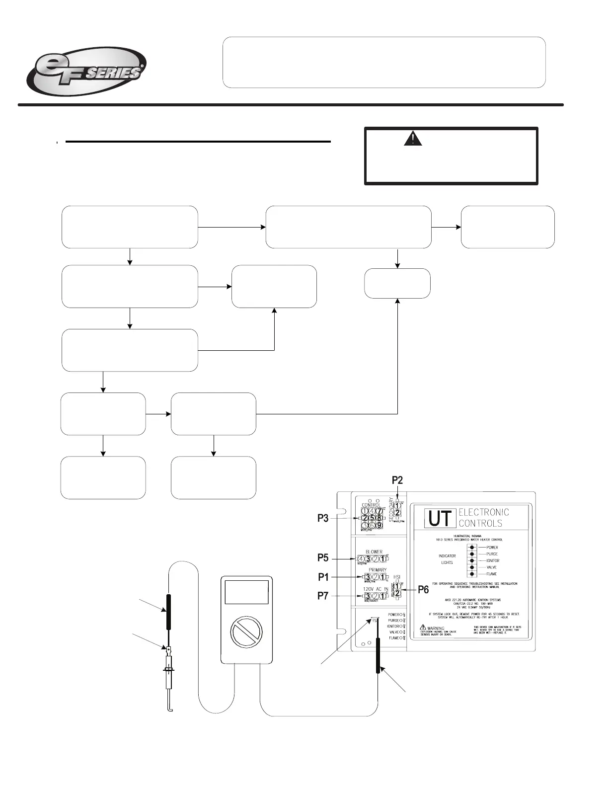
Service Procedure EF-VIII
Flame Sensor Testing and Replacement
Volt meter set to
Micro amps setting
(µA)
Meter probe
Meter probe
Flame sensor terminal
on ignition module.
Flame sensor
terminal
Page 32
Flame Sensor Testing Procedure
Refer to illustration below, is there
a minimum of 1 micro amp during
1.5 second flame proving period?
Y
N
Is flame sensor free
of oxidation?
Clean or replace
flame sensor.
(see pg 33)
N
Is ceramic of flame
sensor cracked?
Replace flame sensor.
(see pg 33)
Y N
Flame sensing circuit OK
Y
Refer to ignition module illustration below. Is
there 24 volts AC at locations P3(2) & P3(5),
24 volts should maintain beyond the 1.5
second flame proving period?
Y
N
Call for
technical support
Replace flame sensor
with gasket
and/or wire lead.
(
see pg 33)
Remove flame sensor from heater.
Check continuity from tip of flame
sensor to end of wire lead.
Is there continuity?
N
Y
WARNING
120 volt potential exposure. Use caution
m
aking voltage checks to avoid
personal injury.
With flame sensor Disconnected
from ignition module, check
continuity to ground.
Is there continuity to ground?
N
Y
Service Procedure EF-VIII
Flame Sensor Testing and Replacement
Volt meter set to
Micro amps setting
(µA)
Meter probe
Meter probe
Flame sensor
terminal on
ignition module.
Flame sensor
terminal
Page 32
Flame Sensor Testing Procedure
Refer to illustration below, is there
a minimum of 1 micro amp during
1.5 second flame proving period?
Y
N
Is flame sensor free
of oxidation?
Clean or replace
flame sensor.
(see pg 33)
N
Is ceramic of flame
sensor cracked?
Replace flame sensor.
(see pg 33)
YN
Flame sensing circuit OK
Y
Refer to ignition module illustration below. Is
there 24 volts AC at locations P3(2) & P3(5)?
24 volts should maintain beyond the 1.5
s
econd flame proving period.
Y
N
Call for
technical support
Replace flame sensor
with gasket
and/or wire lead.
(see pg 33)
Remove flame sensor from heater.
Check continuity from tip of flame
sensor to end of wire lead.
Is there continuity?
N
Y
WARNING
1
20 volt potential exposure. Use caution
making voltage checks to avoid
personal injury.
 Loading...