PROBLEM DETERMINATION
AND
SOLUTION
Precautions
1.
Be
sure
to
turn
the power switch
OFF
before opening
the
control
box.·~over
or
plugging I unplugging
the
power cord.
2.
When replacing a fuse,
be
sure
to
use
a new one having the
same
quality and capacity
as
the old one.
Problem
determination
and
solution
table
• Prior
to
proceeding
to
the
following
table, check
that
---no
fuse
is
blown
---each plug
is
correctly inserted.
• Letters marked
with
an
asterisk (e.g. (a)*) in
the
CHECK
I
ADJUSTMENT
I
REPAIR
column indicate
that
those items should
be
checked
while
the power
is
applied. ·
NO.
IN
CHAPTER
8
FLOWCHART
AND
ERROR
STATUS
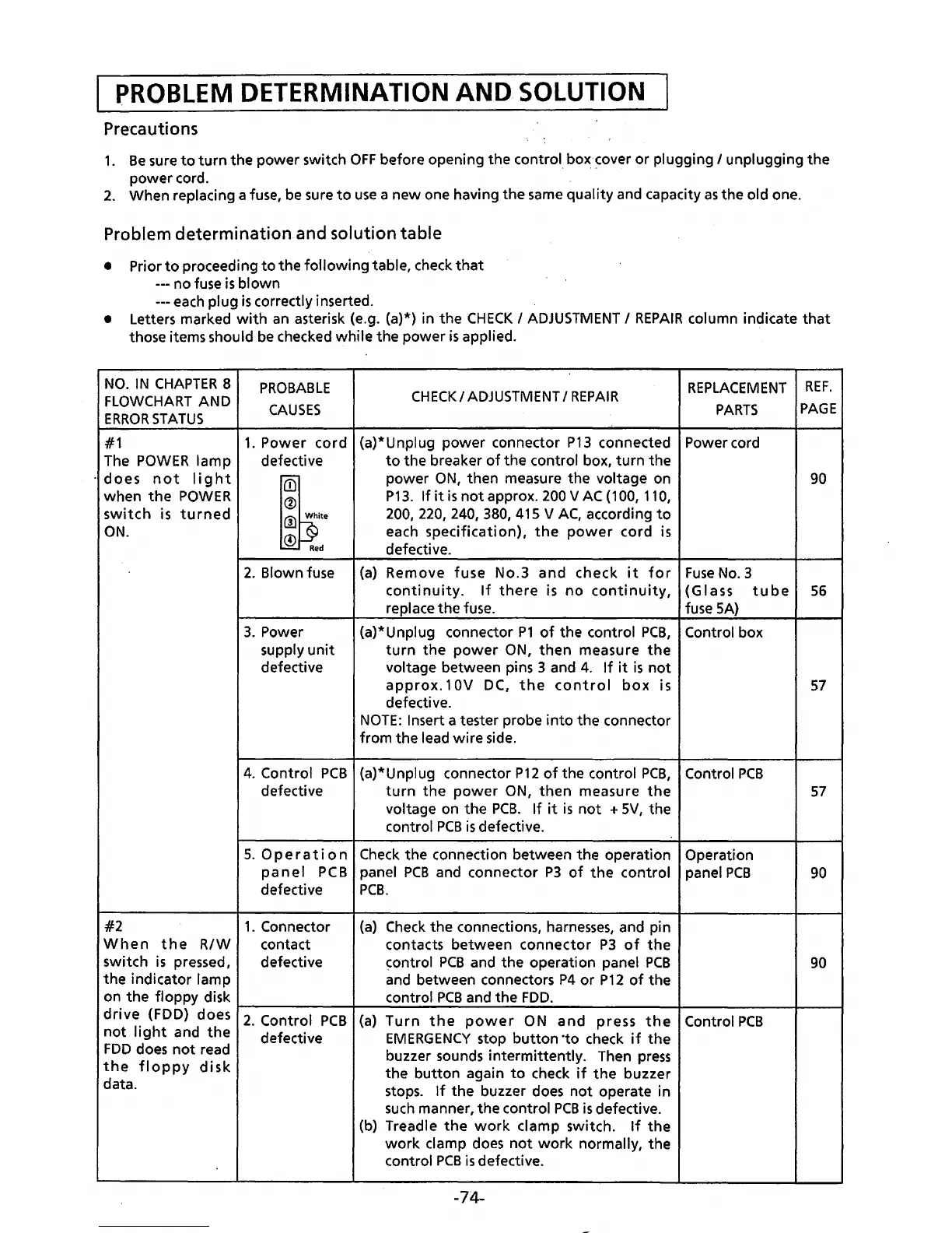
#1
The
POWER
lamp
·does
not
light
when
the
POWER
switch
is
turned
ON.
PROBABLE
CAUSES
1.
Power
cord
defective
{15
®
ro
[§;ite
~
Red
2.
Blown fuse
3.
Power
supply
unit
defective
CHECK/
ADJUSTMENT
I
REPAIR
{a)*Unplug
power
connector
P13
connected
to
the
breaker
of
the control box,
turn
the
power
ON,
then
measure the voltage on
P13.
If
it
is
not
approx.
200
V
AC
(1
00,
110,
200, 220, 240, 380, 415 V
AC,
according
to
each
specification),
the
power
cord is
defective.
(a)
Remove
fuse
No.3
and
check
it
for
continuity.
If
there
is
no
continuity,
replace
the
fuse.
{a)* Unplug connector
P1
of
the control
PCB,
turn
the
power
ON,
then
measure
the
voltage between pins 3 and
4.
If
it
is
not
approx.
1
OV
DC,
the
control
box
is
defective.
NOTE:
Insert a tester probe
into
the
connector
from
the
lead
wire
side.
REPLACEMENT
REF.
PARTS
PAGE
Power cord
90
Fuse
No.3
(Glass
tube
56
fuse
SA)
Control box
57
4.
Control
PCB
(a)* Unplug connector
P12
of
the control
PCB,
Control
PCB
defective
turn
the
power
ON,
then
measure
the
57
voltage on the
PCB.
If
it
is
not
+ 5V, the
control
PCB
is
defective.
5.
Operation
Check
the connection between the operation Operation
panel
PCB
panel
PCB
and connector
P3
of
the
control
panel
PCB
90
defective
PCB.
#2
1.
Connector
(a)
Check
the
connections,
harnesses,
and pin
When
the
R/W
contact contacts
between
connector
P3
of
the
switch
is
pressed, defective control
PCB
and
the
operation panel
PCB
90
the
indicator lamp and between connectors
P4
or
P12
of
the
on
the
floppy disk control
PCB
and the
FDD.
drive
(FDD)
doesr2-_-c_o_n_t-ro_I_P_C_B-+{-a_)_T~u-r_n
__
t_h_e
____
p_o_w_e_r
__
O_N
__
a_n_d
___
p_re_s_s
__
th-e-4-C-o-n-tr_o_IP_C_B--~~----~
not
light
and
the
defective
EMERGENCY
stop
button
·to check
if
the
FDD
does
not
read buzzer sounds intermittently. Then
press
the
floppy
disk
the
button
again
to
check
if
the
buzzer
data. stops.
If
the
buzzer does
not
operate in
such
manner, the control
PCB
is
defective.
(b) Treadle
the
work
damp
switch.
If
the
work
damp
does
not
work
normally, the
control
PCB
is
defective.
-74-
 Loading...