4.
1/0
checking
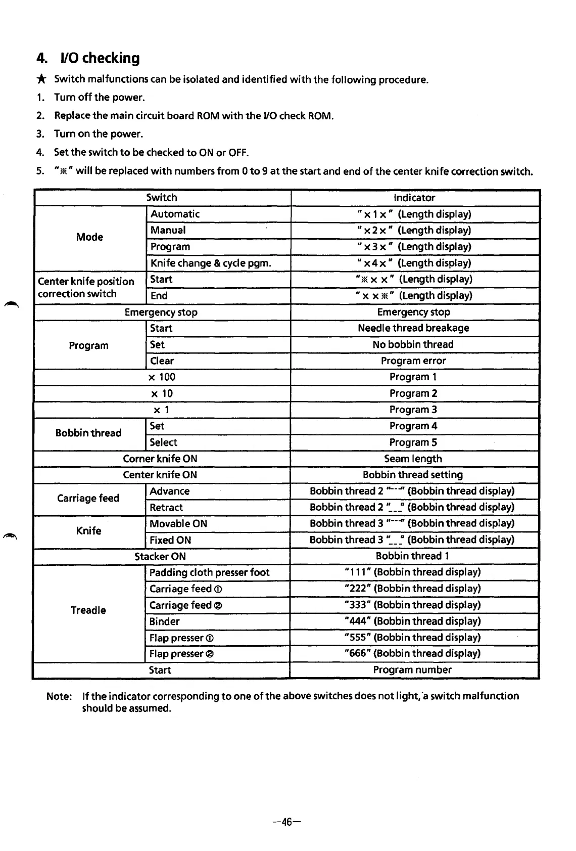
* Switch malfunctions can be isolated and identified
with
the
following
procedure.
1.
Turn
off
the
power.
2.
Replace
the
main circuit board
ROM
with
the
1/0 check
ROM.
3.
Turn on
the
power.
4.
Set
the
switch
to
be checked
to
ON
or
OFF.
5.
"*"will
be
replaced
with
numbers
from
0
to
9
at
the
start and end
of
the
center
knife
correction switch.
Switch
Indicator
Automatic
" x 1 x
11
(Length display)
Mode
Manual
11
x 2 x
11
(Length display)
Program
II
x 3
x"
(Length display)
Knife change & cycle pgm.
II
x 4 x " (Length display)
Center
knife
position
Start
"*
x
x"
(Length display)
correction switch
End
II
x x *" (Length display)
Emergency stop
Emergency stop
Start
Needle thread breakage
Program
Set
No bobbin thread
Clear
Program error
X
100
Program 1
X
10
Program 2
X 1
Program 3
Bobbin thread
Set
Program4
Select
Program 5
Corner knife
ON
Seam
length
Center knife
ON
Bobbin thread setting
Carriage feed
Advance
Bobbin thread 2
,,__..n
{Bobbin thread display)
Retract
Bobbin thread 2
·:-~(Bobbin
thread display)
Knife
Movable
ON
Bobbin thread 3 ,
__
-#{Bobbin thread display)
Fixed
ON
Bobbin thread 3
':-~(Bobbin
thread display)
Stacker
ON
Bobbin thread 1
Padding cloth presser
foot
11
111" (Bobbin thread display)
Carriage feed
<D
"222" {Bobbin thread display)
Treadle
Carriage feed
~
"333" (Bobbin thread display)
Binder
11
444" (Bobbin thread display)
Flap presser
<D
"555" (Bobbin thread display)
Flap presser 0
"666"
(Bobbin thread display)
Start
Program number
Note:
If
the
indicator corresponding
to
one
of
the
above switches does
not
light,
·a
switch malfunction
should be assumed.
-46-
From the library of: Superior Sewing Machine & Supply LLC
 Loading...