STANDARD ADJUSTMENT
(ELECTRONIC
PORTION)
1.
Replacing
the
circuit
board
(1) Replacing
the
main circuit board
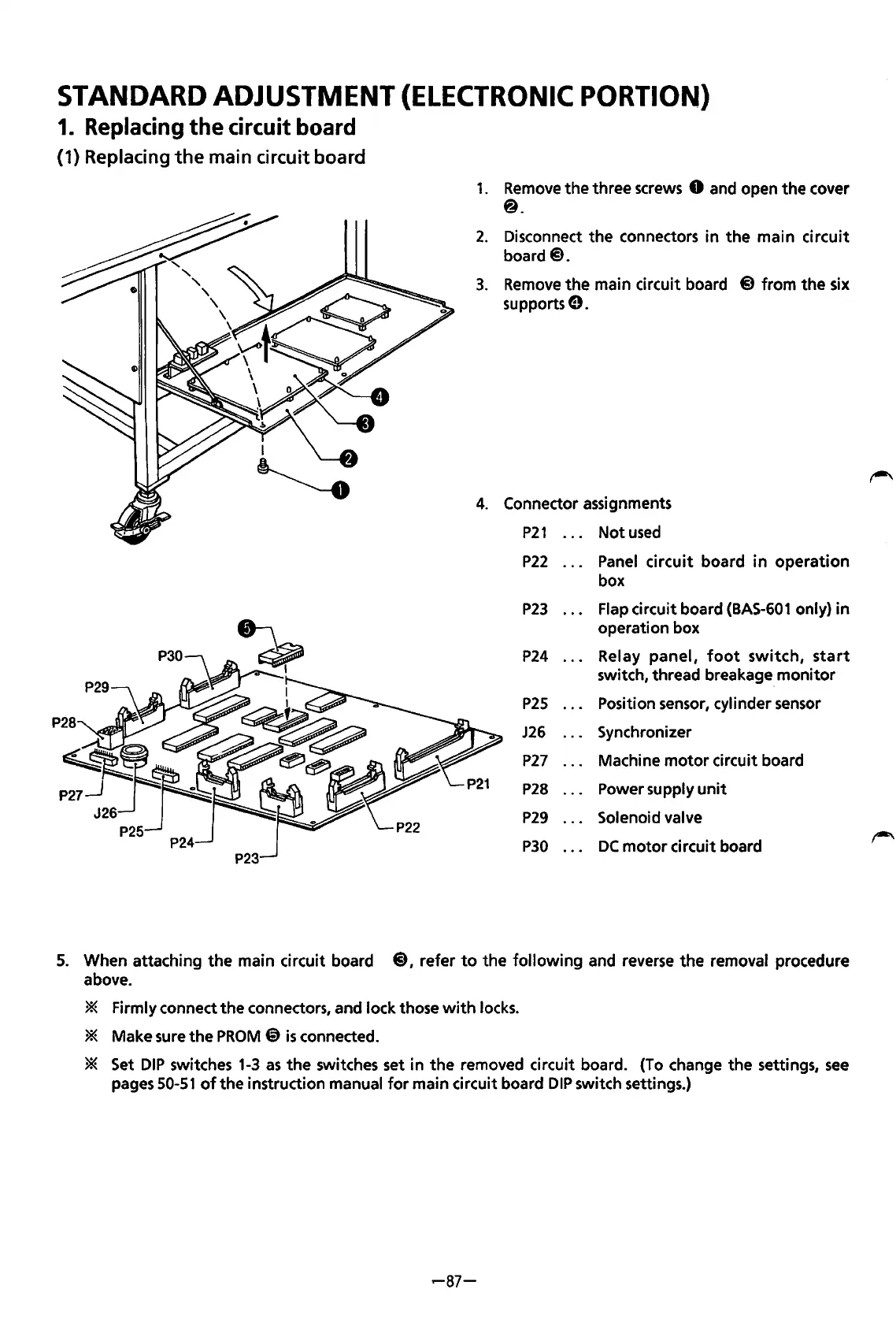
1.
Remove
the three screws 0 and open
the
cover
@.
2.
Disconnect
the
connectors in
the
main
circuit
board@.
3.
Remove
the
main circuit board @)from
the
six
supports
e.
4.
Connector assignments
P21
Not
used
P22
Panel
circuit
board
in
operation
box
P23
Flap circuit board
(BAS-601
only)
in
operation box
P24
Relay
panel,
foot
switch,
start
switch, thread breakage.
monitor
P25
Position sensor, cylinder sensor
J26
Synchronizer
P27
Machine
motor
circuit board
P28
Power supply
unit
P29
Solenoid valve
P30
DC
motor
circuit board
5.
When attaching
the
main circuit board
@),
refer
to
the
following
and reverse the removal procedure
above.
* Firmly connect
the
connectors, and lock those
with
locks.
* Make sure
the
PROM
@
is
connected.
* Set
DIP
switches
1-3
as
the
switches set in
the
removed circuit board. (To change the settings,
see
pages
50-51
of
the
instruction manual
for
main circuit board
DIP
switch settings.)
..--87-
From the library of: Superior Sewing Machine & Supply LLC
 Loading...