SSS
™
1127
|
16
Visit Static Control
®
on the web @ www.scc-inc.com
SSS
™
1127
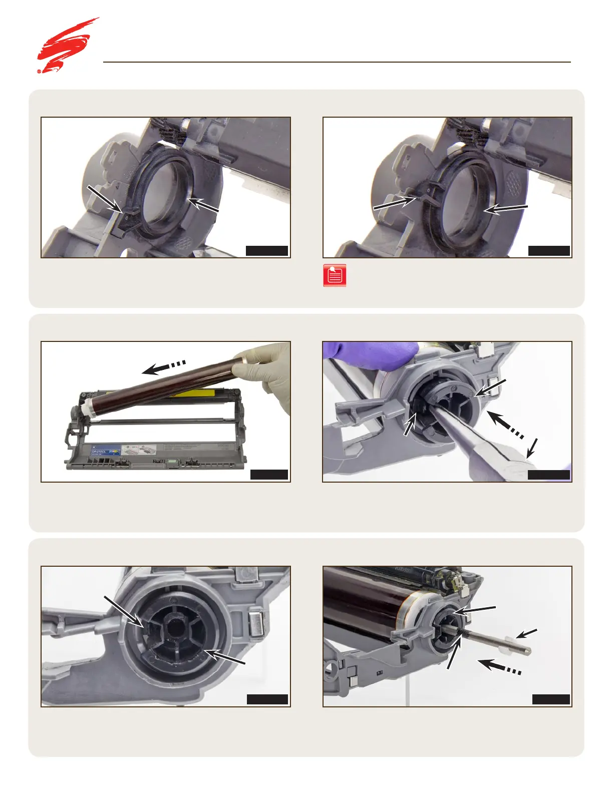
STEP 6.2
STEP 6.1
STEP 6.4
After applying fresh conductive lubricant in the area shown in
Figure 6.4, place the drum axle locking clip onto the drum and
slide the axle into the contact side of the drum.
Place the drum into the drive side of the drum unit first
(Figure 6.2).
Before installing the drum, ensure the stabilizer ring
is positioned correctly on the drive side (Figure 6.1A).
FIGURE 6.2
FIGURE 6.1BFIGURE 6.1A
FIGURE 6.4FIGURE 6.3B
ASSEMBLING THE DRUM UNIT
Note: Incorrect position of the drum stabilizer will
prevent the corona assembly from installing
properly (Figure 6.1B).
Conductive
Lubriacant
Stabilizer Ring
Stabilizer
Ring
correct
Position
incorrect
Position
DRIVE SIDE
DRIVE SIDE
DRIVE SIDE
CONTACT SIDE
Tab
Locking
Bearing
Locking
Bearing
C-Clip
STEP 6.3
Slide the locking bearing into the drum hub (Figure 6.3A).
Secure the locking bearing by aligning the tab on the locking
bearing with the opening in the drum hub (Figure 6.3B).
FIGURE 6.3A
Needle
Nose
Pliers
Tab
Locking
Bearing

 Loading...