0.2 03/2010
© CAME cancelli automatici s.p.a. -
The data and information reported in this installation manual are susceptible to change at any time and without obligation on CAME cancelli automatici s.p.a. to notify users.
ENGLISH
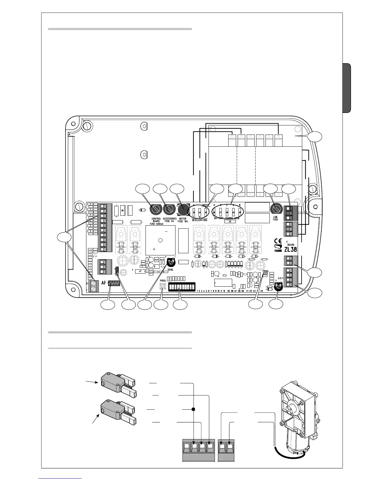
6.1 Main components
1 - Accessories fuse
2 - Line fuse
3 - Control unit fuse
4 - Motor fuse
5 - Accessories terminals
6 - Radio-frequency card input (see table page 19)
7 - SENS Trimmer: adjusts amperometric sensitivity
8 - TCA Trimmer: adjusts automatic closing time
9 - “Function selector” Dip switch
10 - Code storing button
11 - Signalling LEDs for radio codes/automatic closing
12 - Adjustment connectors for deceleration speed
13 - Connectors for LB38 battery charger
14 - Command-type selection jumper for button 2-7
15 - Transformer
16 - Power supply Terminals
17 - Motor Terminals
18 - Endstop Terminals
6.2 Electrical connections
Motor 24V (d.c.)
Gearmotor, endstop
Closing microswitch
Orange
Orange
White
Red
Blue
Brown
Opening micros-
witch
Description of required electrical connections. When installing on the right side, see page 7.
White
Red
Black
Brown
Blue
Brown
 Loading...